 |
|||
|
|
|||
|
|
|||
| ||||||||||
|
|
 CHAPTER 1
INTRODUCTION
Section I. GENERAL
Record Procedures.
1-1. Scope
These instructions constitute the direct and general
support maintenance instructions for the gasoline engine
1-3. Reporting of Errors
powered fork lift truck, pneumatic tires, Baker model
Report of errors, omissions, and recommendations for
FJF-040.
improving this publication by the user is encouraged.
Reports should be submitted on DA Form 2028,
Recommended Changes to Publications, and forwarded
1-2. Maintenance Forms and Records
direct to Commanding General, U. S. Army Mobility
Maintenance forms, records and reports to be used by
Equipment Command, 4300 Goodfellow Boulevard, St.
maintenance personnel at all levels of maintenance are
Louis, Mo. 63120, ATTN: AMSME-MP.
listed in and prescribed by TM 38-750, Army Equipment
Section II. DATA
the truck. Use this table as a guide unless a different
1-4. Tabulated Data
The tables in this section supplement the general data
list component wear limits, fits and tolerances. Some
given in TM 10-3930-627-12. This information covers
press or drag fits do not lend themselves to tabulation,
the critical wear limits, fits and tolerances to be checked
but require narrative explanation.
Such fits are
during overhaul of the fork lift truck. Table 1-1 lists
discussed in text at the point where they are needed.
standard tightening torques for screws and nuts used on
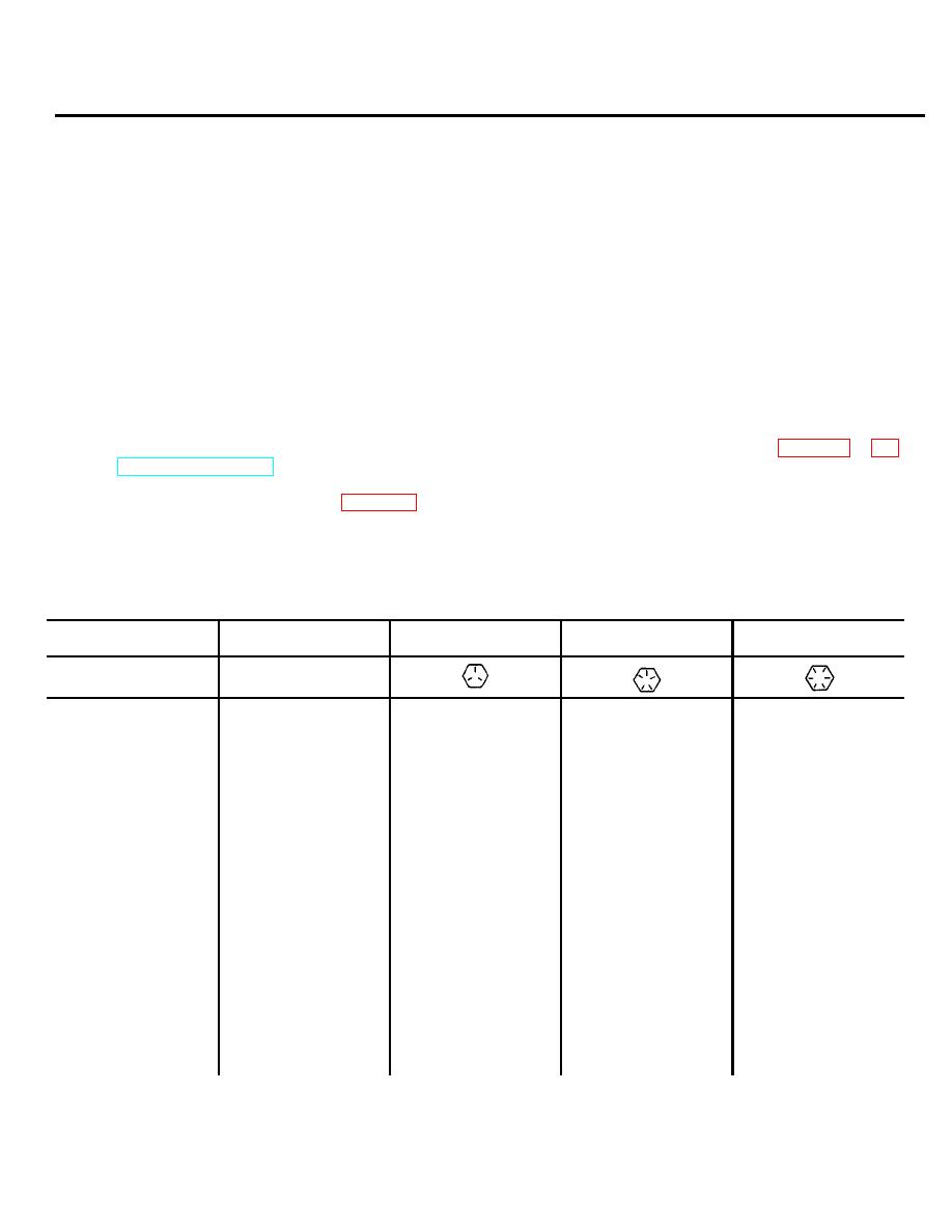
Table 1-1. Torque Values
The following table lists screw torque specifications recommended for all applications where specific torque requirements
are not stated
Screw
Coml low-carb
grade
SAE-2
SAE-5
SAE-7
SAE-8
Head
Marking
None
Screw size
in.-lb.
4-40
8
6-32
12
8-32
20
10-24
25
10-32
30
12-24
35
ft.-lb.
ft.-lb.
ft.-lb.
ft.-lb.
1/4-20
4
7
9
11
1/4-28
5
9
11
13
5/16-18
9
15
19
23
5/16-24
10
17
21
26
3/8-16
15
27
35
42
3/8-24
18
33
42
50
7/16-14
25
45
60
70
9/16-20
30
55
70
80
1/2-13
40
75
90
105
1/2-20
45
85
105
120
9/16-12
60
110
135
150
9/16-18
65
120
150
165
1-1
|
|
Privacy Statement - Press Release - Copyright Information. - Contact Us |
