 |
|||
|
|
|||
|
Page Title:
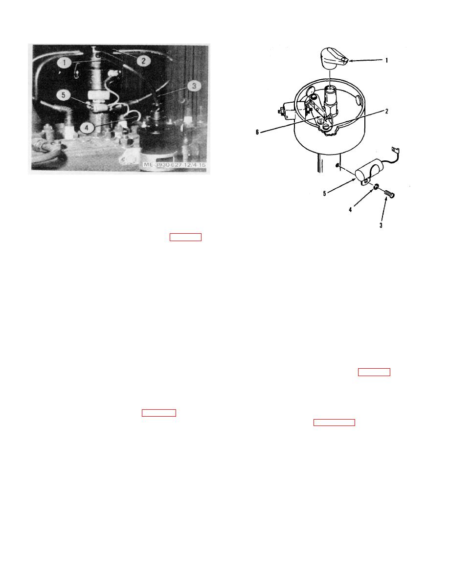
Figure 4-15. Distributor, installed. |
|
||
| ||||||||||
|
|
 TM 10-3930-627-12
1. Suppressor
2. Distributor cap
3. Secondary lead
4. Primary lead
5. Clamp
Figure 4-15. Distributor, installed.
b. Removal.
(1) Disconnect primary lead (4, fig. 4-15) at
1. Rotor
coil and remove secondary lead (3) with suppressor (1)
2. Screw
from the distributor cap (2).
3. Screw
(2)
Remove spark plug cables from
4. Lock washer
distributor cap, noting position of No. 1 cable for
5. Condenser
installation.
6. Contact set
(3) Remove the cap and mark the position
Figure 4-16. Distributor, partly exploded view.
of the rotor in the distributor to facilitate installation. Mark
e. Installation. Reverse procedure in b above
the position of the distributor on the engine block for
and use timing light or static method to determine proper
timing mark on installation of assembly. The firing order
timing (f below).
is 1-3-4-2 in counterclockwise direction looking from the
f. Ignition Timing.
top of the distributor.
(1) Static method. Chalk the timing mark
(4)
Loosen clamp (5) that secures
on the flywheel so the mark can be seen clearly. Remove
distributor to the engine cylinder head.
No. 1 spark plug and place thumb over spark plug hole.
(5) Remove distributor assembly from the
Crank engine until air escapes around thumb. Continue
engine cylinder head.
cranking to align the top- dead-center timing mark with
(6) If necessary, remove the distributor
pointer. Loosen distributor clamp (5, fig. 4-15) and turn
drive shaft from the engine block. Cover the hole in the
the distributor clockwise on its mounting until the contact
engine cylinder head to prevent foreign matter from
points just begin to open. Tighten clamp to secure
entering the block.
adjustment. Replace secondary lead.
c. Disassembly.
(2) Timing light method. Attach a timing
(1) Remove rotor (1, fig. 4-16) from the
light lead to No. 1 spark plug. Connect the other timing
shaft.
light lead as shown in figure 4-17. Connect tachometer
(2) Remove contact set mounting screw (2)
and run engine at 500 rpm. The No. 1 plug should fire
and remove contact set (6).
at top-dead-center. The light should flash each time the
(3) Remove condenser mounting screw
top-dead-center mark on the flywheel passes the pointer
(3), lock washer (4), and condenser (5) from the
on flywheel cover. If adjustment is necessary, loosen the
distributor.
clamp nut and turn the distributor at its mounting. Rotate
(4) Remove distributor primary lead and
the
grommet through the inside of the distributor.
d. Assembly. Reverse procedure in c above
and adjust points (g below).
4-21
|
|
Privacy Statement - Press Release - Copyright Information. - Contact Us |
