 |
|||
|
|
|||
|
|
|||
| ||||||||||
|
|
 TM 10-3930-627-12
c. Transmission. This is a constant mesh,
d. Drive Axle. The drive (front) axle is a double
power shifted unit with forward, reverse, and neutral shift
reduction heavy duty industrial unit, fitted with dual
positions available. Engine output is sent through a
wheels to support the weight of the truck plus load. The
torque converter to the transmission, which delivers it to
wheels of this axle are fitted with self- adjusting hydraulic
the front, or drive axle. Since all transmission gears are
brakes.
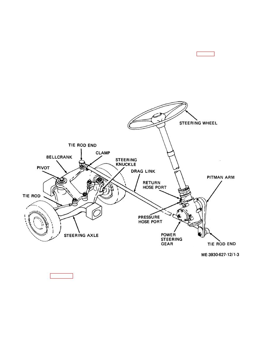
e. Steering Axle (fig. 1-3). The rear axle is
in constant mesh, they are coupled, when drive is
needed, by hydraulic application of internal clutches.
steerable, for greatest maneuverability in limited working
Operation of the shift lever on the steering column works
space.
Steering geometry is neutral; there is no
a selector valve on the transmission which applies and
tendency for the wheels to return to straight ahead
releases the drive clutches needed for forward or reverse
position when the steering wheel is released. A Saginaw
travel. In neutral the valve simply dumps all pressure.
power steering gear operates the steering axle.
Since the transmission fluid may get quite hot when
working hard, it is circulated through a cooler on the
truck radiator.
Figure 1-3. Steering System.
f. Mast (fig. 1-4). This is the load handling
The entire mast as a unit can be tilted forward when
slipping the forks under a load, then tilted back to cradle
system of the truck. Two forks are attached to a carriage
the load when hoisting or traveling. A two-handled
which is raised by a hydraulic cylinder. Two channel iron
control valve at the right of the driver's seat controls lift,
upright members guide the carriage in its travel, the
and tilting of the mast.
channels acting as guide rails for rollers on the carriage.
1-5
|
|
Privacy Statement - Press Release - Copyright Information. - Contact Us |
