 |
|||
|
|
|||
|
|
|||
| ||||||||||
|
|
 slack when the spring is attached to the brake crank
(2) Remove pin and cotter pin, loosen the
assembly. Adjust the linkage after installation.
jam nut, and rotate lower yoke (8 fig. 4-3) to adjust brake
shoe position.
4-31. Service Brakes
c. Cleaning and Inspection.
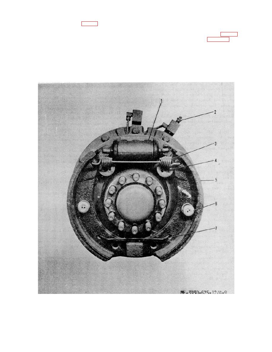
a. Removal of Shoe Assembly (fig. 4-9).
(If Clean with an approved cleaning solvent (Federal
(1) Remove wheel (para 4-37).
Specification P-D-680) and dry thoroughly.
(2) Remove return spring.
(2) Inspect for worn cable, breaks, cracks,
(3)
Remove retainers, springs and
or other defects.
washers.
(3) Replace defective parts as necessary.
(4) Remove brake shoes.
d. Installation. Installation is the reverse of
(5). Remove retainer spring.
removal. With seat down and directional control switch
in either forward or reverse, there should be very little
2. Bleed valve
4.
Cam adjusting bolt
6. Retaining spring and
1. Wheel cylinder
3. Shoe return spring
assembly
washers
5. Brake shoe
7. Retainer spring
Figure 4-9. Service brakes.
4-17
|
|
Privacy Statement - Press Release - Copyright Information. - Contact Us |
