 |
|||
|
|
|||
|
|
|||
| ||||||||||
|
|
 (5) Install the radiator grille (TM 10-3930-
624-12).
(6) Check the oil reservoir to be sure the oil
level is correct. Run the pump for one minute with
no load to allow the system to fill. Check the inlet
and outlet ports for leaks. Tighten the connections
to eliminate any leaks. If the pump is cavitating,
tighten the inlet line at the pump. After one minute
of running, shut down the engine and recheck the
oil level in the reservoir. If it is low, fill to the proper
level. If severe foaming is noted, check for a leak in
the inlet line or for improper oil. Refer to the
current LO 10-3930-624-12 for the proper oil.
5-6. Control Valve
a. Removal.
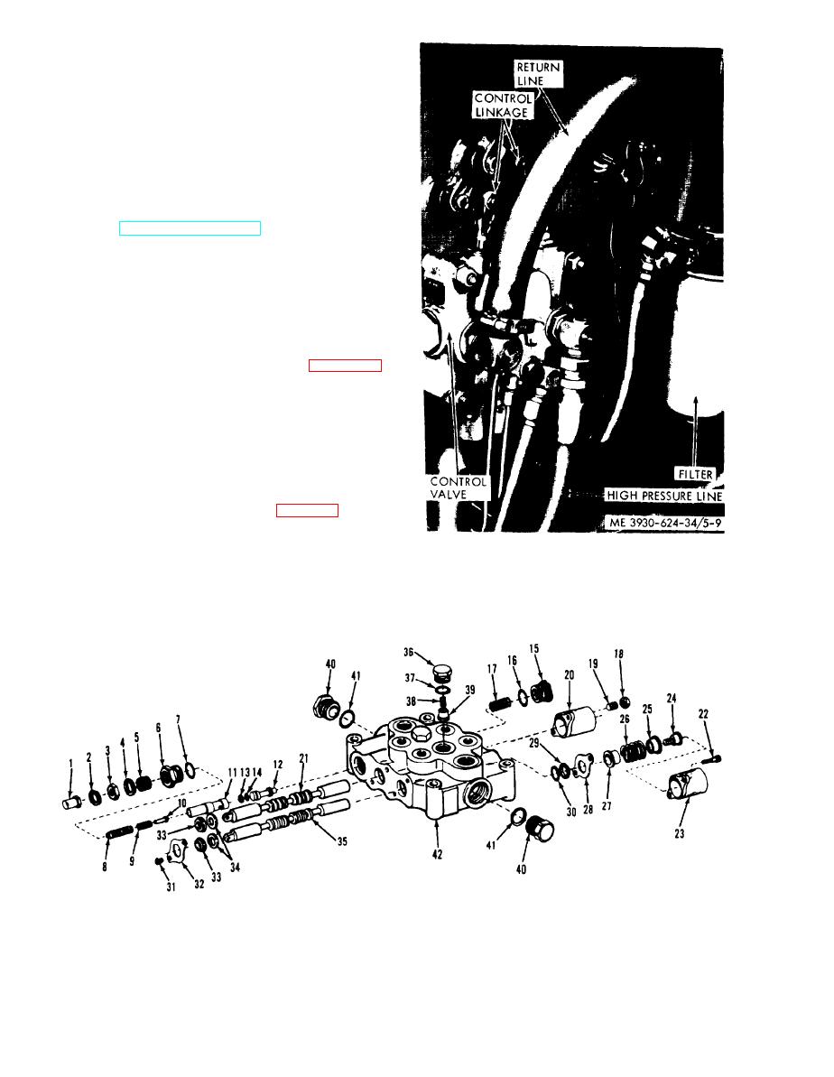
Note. Before removing the valve make sure that the lift
cylinders are collapsed. Tilt the mast backward and forward to
relieve the pressure in the control valve.
(1) Disconnect the control linkages at the
valve spool connections as shown in figure 5-9.
(2) Tag and disconnect all hydraulic lines to
the control valve. Cap or plug openings.
(3) Remove the mounting hardware and the
control valve.
b. Disassembly.
(1) Clean the exterior of the control valve and
dry with compressed air. Clamp the valve in a vise.
Be careful not to damage the housing.
(2) Remove the cap nut (1, fig. 5-10), washer
(2). locknut (3). washer (4), plug (5) and plug (6).
Remove the preformed packing (7) from the plug.
Figure 5-9. Control valve.
ME 3930-624-34/5-10
Figure 5-10. Control valve, exploded view.
5-10
|
|
Privacy Statement - Press Release - Copyright Information. - Contact Us |
