 |
|||
|
|
|||
|
|
|||
| ||||||||||
|
|
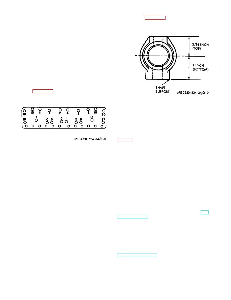 cylinder head, m a k i n g c e r t a i n t h a t t h e s h a f t
installed, chill the inserts in dry ice. Start the inserts
supports are positioned with the longer section
into the counterbore (valve seat side up). Using a
down. Refer to figure 3-9.
valve seat installation tool, drive the insert down
tightly into the counterbore. Stake the valve seats in
position using a center punch. Stake at two or three
points around the edge of the seat. Refinish the
valve seat inserts.
(4) Install the valves (30 and 31) in their
original positions. Install the springs (29), retainers
(28) and locks (27). Using a spring compressor,
compress the springs and install the caps (26).
(5) Assemble remaining components in the
reverse order of disassembly.
e. Installation.
(1) Clean the top of the cylinder block.
foreign objects before installing the head.
(2) Install guide studs in holes 11 and 12.
Refer to figure 3-8.
Figure 3-9. Rocker arm shaft support installation.
Caution: The rocker arms are not
designed to contact the valve stems at the
center, but 1/16 inch off center. Do not bend
the rocker arms to make them line up center to
center with the valve stems.
(11) With the valve lash adjusting screws (13,
tighten the shaft support stud nuts and capscrews
to a torque of 18 to 22 ft Ibs.
Figure 3-8. Guide stud location and torquing sequence.
(12) Install the oil tube between the rocker
arm shaft and cylinder head.
(3) Be sure the new cylinder head gasket is
(13) Connect the rocker arm oil feed line from
installed with the proper side up. The gasket is
the head.
marked to indicate which side is to be installed on
(14) Install the thermostat housing. Connect
the cylinder block. Do not use any sealer or gasket
the coolant outlet tube from the thermostat housing
dope on any part of the cylinder head gasket
to the radiator. Install the coolant bypass tube and
assembly. A thin coat of light grease may be used
connect the lead at the coolant temperature sending
on the top deck of the cylinder block around the
unit.
cylinder bores.
(15) Install the manifold. Refer to TM 10-
(4) Position the fire rings inside the cylinder
3930-624-12.
bores of the gasket and ensure that the gasket does
(16) Close the drain cocks and refill the
not overlap the fire rings.
cooling system with the proper coolant.
(5) Lower the cylinder head to the block with
(17) Adjust the valve clearance. Refer to TM
the aid of a sling. The head should be properly
10-3930-624-12.
located by the guide studs.
(18) Install a new rocker arm cover gasket.
(6) Install the capscrews in all locations
Install the rocker arm cover and vent hose.
except those occupied by guide studs.
(19) Install the seat and seat deck, air cleaner,
(7) Remove the guide studs and install the
and side panels.
remaining capscrews. Tighten the capscrews in the
3-13. Timing Gear Assembly
specified numerical sequence (fig.3-8) to 55 ft Ibs.
(8) Retighten the capscrews, in numerical
a. Removal.
(1) Remove the radiator and fan belt. Refer to
sequence, to a final torque of 110 ft Ibs.
TM 10-3930-624-12.
(9) Install the push rods and make sure they
(2) Remove t h e h y d r a u l i c p u m p a n d
seat properly in the lifters.
crankshaft pulley.
(10) install the rocker arm assembly on the
3-12
|
|
Privacy Statement - Press Release - Copyright Information. - Contact Us |
