 |
|||
|
|
|||
|
|
|||
| ||||||||||
|
|
 b. Cleaning and Inspection.
(1) Wipe the tie rod ends with a cloth
dampened with a cleaning solvent. Clean all remaining
parts with solvent and air dry.
(2) Inspect the tie rod ends for damaged
threads, binding or seizing of the studs, scoring or
corrosion. If tie rods are bent or damaged, they are to
be replaced.
c. Reassembly, Installation and Adjustment.
(1) Reassemble the locknuts and tie rod ends
on the tie rods. Do not tighten the locknuts until the tie
rod length is adjusted.
(2) To adjust the tie rods, raise the truck with
a jack under the counter-weight to raise the steering
wheels from the floor. Disconnect the power steering
cylinder from the pivot arm assembly, as directed in
(3) Place the wheels in a straight ahead
position, so that they will track with the drive wheels.
Install the tie rods between the steering knuckles and
the pivot arm assembly. If one wheel remains in a
straight position and the other is turned slightly in or
outward, adjust the tie rod of the wheel that is not
straight, as zero degrees toe-in must be maintained at
all times.
(4) To adjust the tie rod (fig. 4-56) loosen the
adjustment plug and remove the rod from the pivot arm
assembly. Swing the tie rod away from the steer axle.
Align the steer wheel so that they are parallel with the
side of the truck. Turn the tie rod on to the ball socket to
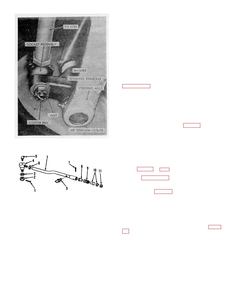
Figure 4-55. Tie rod removal (steering knuckle end).
shorten the tie rod, or turn the rod off of the ball socket
to lengthen the tie rod.
(5) After the correct adjustment has been
achieved, tighten the locknuts and replace the tie rod on
the pivot arm assembly. Tighten the adjustment plug
(6) Adjust and install the steering cylinder as
directed in paragraph 4-59.
4-59. Power Steering Cylinder
(1) Remove the inlet and outlet lines from the
1.
Cotter pin
7.
Tie rod
power steering cylinder; allowing the lines and cylinder
2.
Nut
8.
Plug
to drain into a container of suitable size.
3.
Washer
9.
Spring
Plug the ends of the lines and the cylinder ports to keep
4.
Socket assembly
10.
Ball seats
out foreign matter.
5.
Grease fitting
11.
Adjusting plug
(2) Disconnect ball socket connecting the
6.
Adjusting nut
power steering cylinder to the pivot arm, by removing
the cotter pin and loosening the adjusting plug (fig. 4-
Figure 4-56. Tie rod assembly.
(3) To disconnect the front end of cylinder
from the frame, remove the cotter pin securing shaft pin
in bracket.
4-46
|
|
Privacy Statement - Press Release - Copyright Information. - Contact Us |
