 |
|||
|
|
|||
|
|
|||
| ||||||||||
|
|
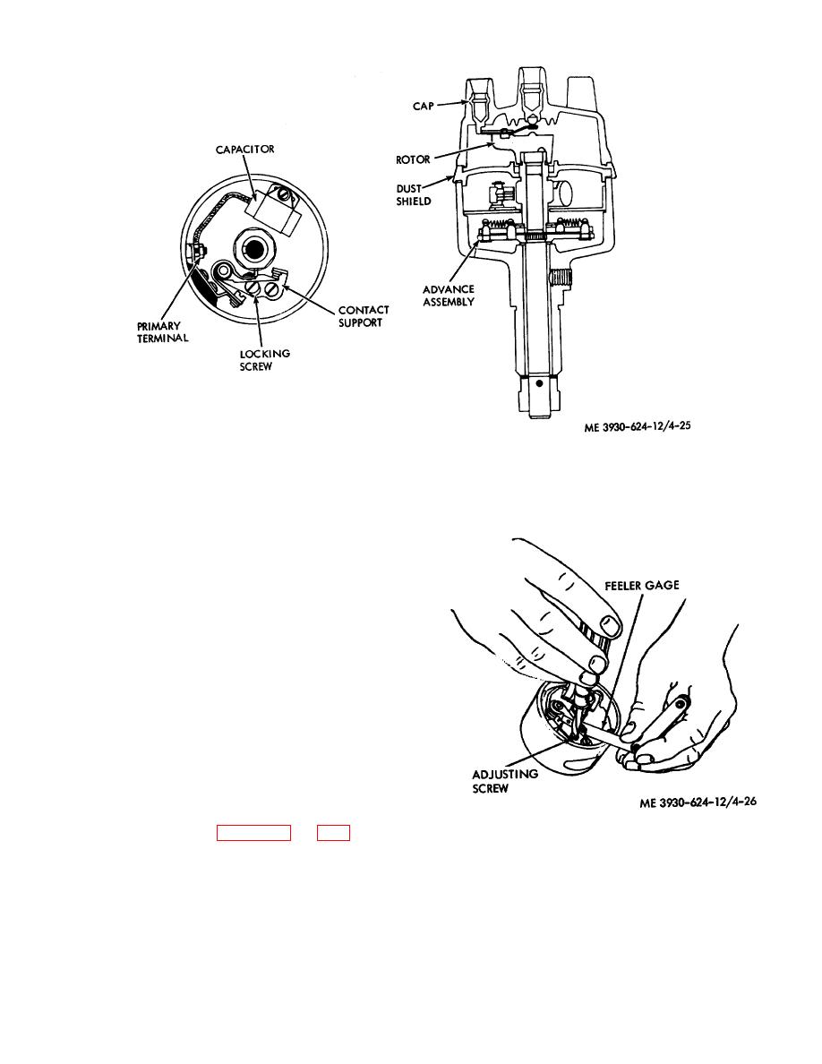 Figure 4-25. Distributor.
(3) Remove the slotted head locking screw
attaching the contact support to the distributor breaker
plate, and remove the contact points. If the capacitor is
to be replaced, remove the screw attaching the
capacitor to the breaker plate and remove the capacitor.
(4) Apply a light coat of grease to the
distributor cam. Install a new capacitor. Install a new
contact support over the pivot post and start the slotted
head locking screw attaching contact support to breaker
plate, but do not tighten the screw at this time. Install
the breaker lever over the pivot post and over the inner
end of the primary terminal. Install and tighten the nut
on the primary terminal.
(5) Rotate the crankshaft until the breaker
lever rubbing block is on a high spot on the cam, thus
opening the contact points to their maximum open
position. Turn the eccentric adjusting screw to obtain
the specified contact point gap of 0.016 in. Lock the
points in position by tightening the contact plate locking
screw.
After tightening contact plate locking screw,
recheck point gap. Refer to figures 4-26 and 4-27.
Figure 4-26. Adjusting contact gap.
4-29
|
|
Privacy Statement - Press Release - Copyright Information. - Contact Us |
