 |
|||
|
|
|||
|
Page Title:
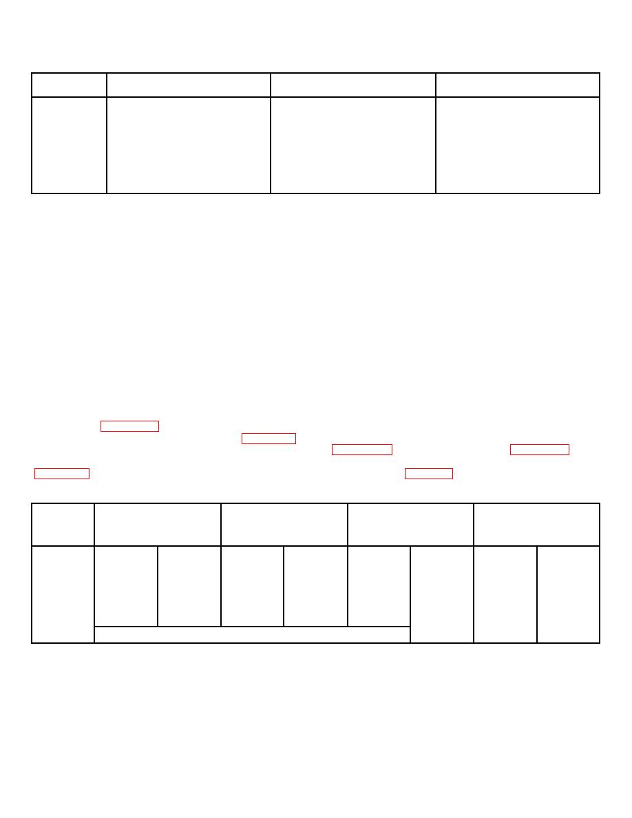
Figure 7-9. Table of Engine Dynamometer Run-In Procedures |
|
||
| ||||||||||
|
|
 TM 10-3930-623-34
Manifold Vacuum In
Step
Time
Inches of Mercury
RPM
1
Warm-up period 10 minutes
No load
600 to 800
2
10 minutes
15 inches
1500
3
15 minutes
10 inches
2000
4
15 minutes
10 inches
Governed speed
5
30 minutes
6 inches
Governed speed
6
10 minutes
Open throttle (full load)
Governed speed
Figure 7-9. Table of Engine Dynamometer Run-In Procedures
1. Road test transmission for satisfactory operation
NOTE
in forward and reverse operation, and for unusual
noises.
If more than one gage is available, all
pressure points may be tested at one
2. With brakes applied, and transmission engaged,
time.
first in forward, then in reverse, check stall speed, or
maximum speed at which engine will operate loaded by
7-87. INCHING VALVE ADJUSTMENT. The inching
the torque converter. With oil temperature at 200 deg F,
control valve spool is limited to a travel of 0.50 inches.
engine speed should be between 1615 rpm and 1785
rpm.
Higher stall speed indicates slippage in the
During this travel, controlled by the brake pedal, the
transmission clutches, defective control valve, linkage
master cylinder push rod must be free to insure
maladjustments, or low fluid level in the transmission.
complete release of the brakes. Adjust as follows:
Lower stall speed indicates engine lacks normal power,
and must be repaired before results of this test are valid.
1. Check brake pedal to insure pedal arm will be
parallel to the underside of the floor plate with 1/8 inch
3. If stall speed is high, test pressures for values
clearance. Adjust pedal stop bolt as required.
indicated in figure 7-9.
Points at which pressure
measurements are made are shown in figure 1-7.
2. Adjust inching control valve piston (23,
Remove plug in passage to be tested, install pressure
gage, and operate engine at speed specified in
spool is fully in when screw is against the brake pedal
inching rod (16, figure 7-8).
Converter
Engine
Main Line
Charging
Forward Clutch
Reverse Clutch
RPM
Pressure (PSI)
Pressure (PSI)
Pressure (PSI)
Pressure (PSI)
Min
Max
Min
Max
Min
Max
Min
Max
500
20
30
15
25
15
25
15
25
1000
58
68
42
50
50
58
50
58
1500
110
120
74
84
77
87
77
87
2000
120
135
84
101
80
93
80
93
With inching valve fully actuated
200
0
0
Figure 7-10. Table of Transmission Test Pressures
7-21
|
|
Privacy Statement - Press Release - Copyright Information. - Contact Us |
