 |
|||
|
|
|||
|
Page Title:
STARTING MOTOR ARMATURE INSPECTION AND TEST |
|
||
| ||||||||||
|
|
 TM 10-3930-623-34
2. Check all lead wires for fraying, broken strands,
4. Check armat ure assembly for open coils and
or corrosion. Discard defective lead wires.
shorts and grounds using conventional test light and
growler tests.
3. Discard broken or bent springs and brush
holders. Measure spring tension with a spring gage.
CAUTION
Discard springs if pressure of brushes to cummutator is
less than 35 ounces, or if springs are discolored or
Do not touch test lamp probes to
distorted.
shaft bearing surfaces. Arcing will
damage smooth surfaces.
4. Examine commutator end bell for cracks,
distortion, or excessive side plan. Discard if damaged or
7-27.
STARTING
MOTOR
worn.
INSPECTION.
7-26. STARTING MOTOR ARMATURE INSPECTION
1. Check starting switch terminals and terminal
AND TEST.
nuts for stripped or crossed threads. Discard parts,
which cannot be repaired.
1. Check bearing surface at ends of shaft for pitting
and scoring. Examine shaft for straightness. Discard
2. Use a conventional test light and a 12 volt
armature (34, figure 4-21) if pits or scratches cannot be
battery to check circuit continuity of switch and relay. If
repaired with a fine grade hone, or if shaft is bent.
the test lamp does not light when switch is closed,
2. Examine commutator for roughness, high mica,
discard switch.
and burning. If commutator is dirty or discolored, clean
with 00 sandpaper. Check commutator with a dial
indicator for out-of-round. If out-of-round exceeds 0.003
7-28.
STARTING
MOTOR
DRIVE
ASSEMBLY
inch, turn down commutator on lathe, and undercut mica
INSPECTION.
1/16 inch between segments.
1. Examine drive pinion and shaft assembly for
3. Examine all windings for properly soldered
worn or broken teeth. Check movement by rotating drive
connections.
pinion. Discard defective or damaged assembly.
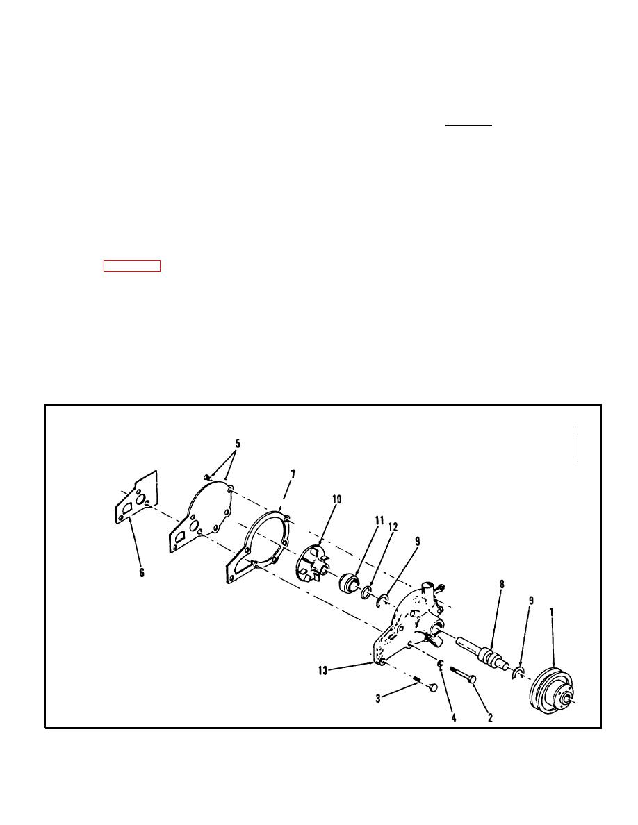
1.
Drive Pulley
2.
Screw
3.
Screw
4.
Washer
5.
Rear Cover
6.
Gasket
7.
Body Gasket
8.
Bearing and Shaft
9.
Retaining Ring
10.
Pump Impeller
11.
Pump Seal
12.
Gasket
13.
Pump Body
Figure 7-4. Engine Water Pump, Exploded View
7-10
|
|
Privacy Statement - Press Release - Copyright Information. - Contact Us |
