 |
|||
|
|
|||
|
Page Title:
Figure 4-21. Engine Electrical Starting Motor. Exploded View |
|
||
| ||||||||||
|
|
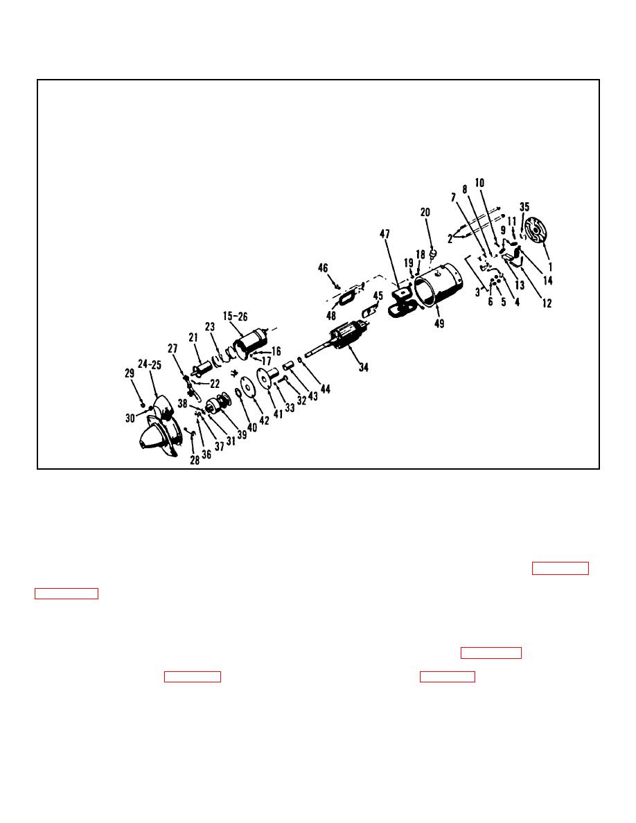 TM 10-3930-623-34
1. End Bell
21.
Solenoid Plunger
36.
Thrust Collar
43.
Bearing
2. Through Bolt
22.
Pin
37.
Retaining Ring
44.
Bearing Seal
3. Brush Support
23.
Spring
38.
Stop Collar
45.
Pole Shoe
4. Ground Lead
24.
End Bell
39.
Drive Assembly
46.
Screw
5. Nut
25.
Bearing
40.
Washer
47.
Winding Field Coils
6. Lock Washer
26.
Solenoid Boot
41.
Bearing Plate
48.
Winding Insulator
7. Screw
27.
Pinion Lever
42.
Gasket
49.
Starter Housing
8. Pin
28.
Screw
9. Contact Brush
29.
Nut
10. Screw
30.
Washer
11. Screw
31.
Pin
12. Brush Spring
32.
Screw
13. Grounded Brush Holder
33.
Lock Washer
14. Insulated Brush Holder
34.
Armature
15. Relay-Solenoid
35.
Brake Washer
16. Screw
17. Lock Washer
18. Grommet
19. Lock Washer
20. Screw
Figure 4-21. Engine Electrical Starting Motor. Exploded View
3. Remove spark plugs.
4-84. ENGINE DISASSEMBLY,
4-85. CYLINDER HEAD.
4-88.
VALVES
AND
RELATED
COMPONENTS
REMOVAL.
4-86. REMOVAL
1. Remove valve chamber cover (15, figure 4-22).
1. Remove cylinder head screws (4, 53, and 54,
2. Plug valve chamber oil return holes to prevent
cylinder head (52) and gasket (59) from engine cylinder
parts falling into oil pan.
block (62).
3. Rotate crankshaft until lowest point of any lifter
travel is reached.
Using valve spring compressor,
4-87. DISASSEMBLY.
compress valve spring (5, figure 4-23). Remove valve
1. Remove stud nuts and lock washers and
locks (7).
Release and remove valve spring
remove elbow (housing) (27 figure 4-22) and thermostat
compressor. See figure 4-24. Remove remaining locks
from cylinder head (52).
in a similar manner.
2. Remove engine temperature transmitter from
4. Lift exhaust valves (2) and intake valves (1) out
the cylinder head.
through top of cylinder block and tag them for installation
in original positions.
4-26
|
|
Privacy Statement - Press Release - Copyright Information. - Contact Us |
