 |
|||
|
|
|||
|
|
|||
| ||||||||||
|
|
 TM 10-3930-623-34
1-6. The fork lift trucks are powered by a Continental
FS-244 Military Standard engine.
1-7. DETAILED DESCRIPTION.
The Continental FS-244 Military Standard engine is
rated at 82.3 horsepower when operating at 2800
revolutions per minute.
1-9. The full pressure lubrication system includes a
gear-type oil pump with adjustable bypass valve to
maintain suitable pressure through all speeds, and a
replaceable element oil filter.
1-10. The fuel system includes a mechanical diaphragm
fuel pump, driven by the engine camshaft, a single
venturi updraft carburetor, and a mechanical governor
which limits the maximum speed of the engine by closing
the carburetor throttle valve when the engine reaches
the governed speed. The carburetor air cleaner uses a
disposable paper filter element.
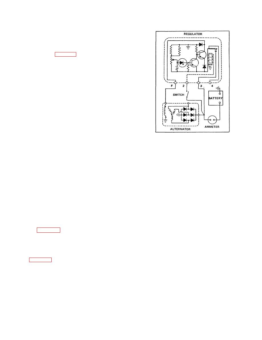
Figure 1-3. Charging System Basic Schematic
designed and constructed to give long service with a
minimum of maintenance. The rotor is mounted on a
ball bearing at the drive end, and a roller bearing at the
The flow of current to the field circuit of the alternator
slip ring end, and each bearing has a grease supply
provides the magnetic field for the alternator. When the
which eliminates the need for periodic lubrication. Two
engine is started, the alternator builds up voltage. This
brushes are used to carry current through the two slip
causes current to flow to charge the battery and/or
rings to the field coil which is mounted on the rotor. The
power accessories.
brushes are extra long and under normal operating
conditions will provide long periods of service. The
2. As alternator speed increases or the accessory load
stator windings are assembled on the inside of a
decreases, alternator voltage builds up to a
laminated core that forms part of the frame. Six rectifier
diodes, mounted in the slip ring end frame, are
predetermined value at which the regulator is set or
connected to the stator windings. The six diodes change
adjusted. The electrical control portion of the regulator
the ac voltage to dc voltage which appears at the BAT
then places a higher voltage on the base of the transistor
terminal on the alternator. A capacitor, or condenser,
than is impressed upon the emitter, and the transistor is
mounted in the end frame protects the diodes from high
turned "off". With no current flow in the emitter-collector
voltages. Current output of the alternator is self4-limiting
circuit, there is no current flow in the field coil of the
by design to its rated maximum, regardless of speed or
alternator. As a result, alternator voltage drops below
external circuit conditions.
An externally mounted
the setting or adjustment of the regulator.
voltage regulator limits the operating voltage to a
specified value through the full speed range of the
3. Then the electrical control portion of the regulator
alternator. Figure 1-3 shows a schematic view of the
alternator and regulator.
places a lower voltage on the base of the transistor than
that on the emitter, and the transistor is again turned
1-12. VOLTAGE REGULATOR. The transistor is an
"on". With current flow again in the emitter-collector and
electrical device made of semiconductor materials which
field coil circuit, the magnetic field is reestablished in the
is used as a switch to control the alternator field current
-alternator, and alternator voltage can again build up to
in order that alternator voltage can be limited to a proper
the setting of the regulator.
value. Figure 1-3 is a greatly simplified diagram of the
alternator and regulator circuit. A brief description of the
4. Thus, the switching "on" and "off' of the transistor
operation follows:
regulates the amount of field current supplied to the
alternator. The frequency of this switching is dependent
1. When the ignition switch is closed, battery voltage
primarily upon the accessory load and alternator speed.
supplies current through the emitter (E) and collector (C)
Under certain conditions the "on" and "off' cycle is
of the transistor to the field coil of the alternator. This
repeated-as much as 7,000 times per second.
emitter-collector circuit is complete since the transistor is
turned "on" by a higher voltage on the emitter than on
the base (B), which permits emitter-base current to flow.
1-3
|
|
Privacy Statement - Press Release - Copyright Information. - Contact Us |
