 |
|||
|
|
|||
|
Page Title:
Figure 6-40. Valve Installation |
|
||
| ||||||||||
|
|
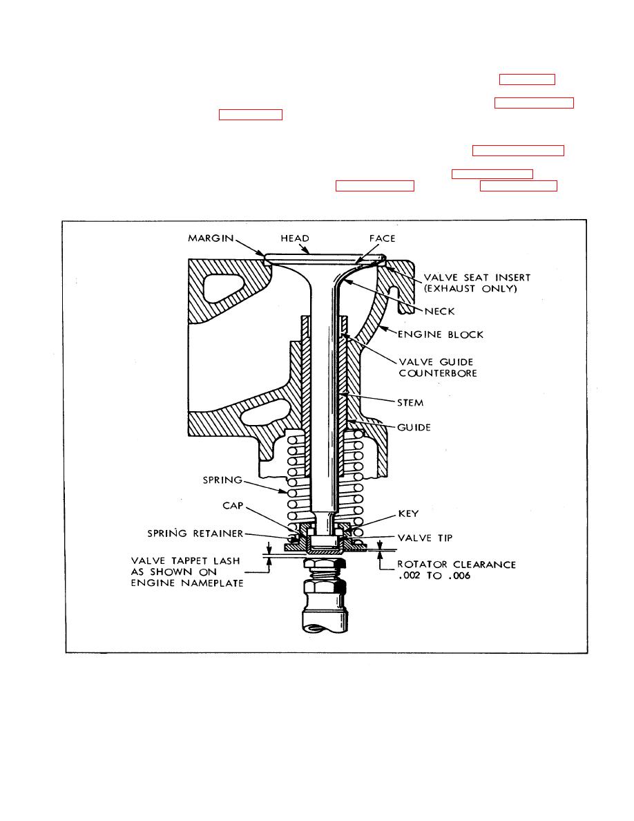 (c) After installation, ream bore of new guides
(2) Raise and lower valve with fingers, noting
to 0.002 inch larger than stem of valve to be installed.
indicator reading total. If not between 0.002 and 0.006
e. Installation. Reverse b (2) above, perform f
inch, adjust as required as shown in figure 6-41.
below, then reverse b(l) above.
f. Check and adjustment, rotator cap clearance.
g. Valve adjustment. Refer to paragraph 6-77.
(1) Set up a dial indicator (Figure 6-41) to
contact top of installed valve, and turn engine until valve
6-84.
ENGINE ASSEMBLY.
opens. Valve is now free to turn, and can be moved
vertically through rotator clearance, if any exists.
a. Install crankshaft Paragraph 6-81f) and
b. Install camshaft (Paragraph 6-79c), gear cover
Figure 6-40. Valve Installation
112
|
|
Privacy Statement - Press Release - Copyright Information. - Contact Us |
