 |
|||
|
|
|||
|
|
|||
| ||||||||||
|
|
 TM 10-3930-621-34
(3) Aline pins and install bull gear (2) to wheel
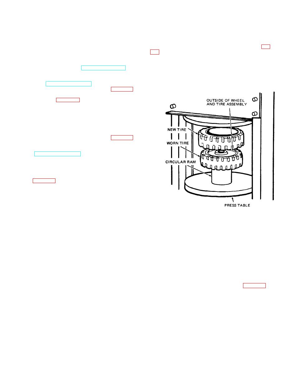
f. Position new tire on top of wheel and old tire
(4) using screws (6) from other side of wheel.
assembly. Aline new tire and the wheel and old tire
Tighten screws evenly and in sequence. (4) Remove
assembly so that they are concentric with each other (fig.
screws (6) and secure bull gear (2) to wheel (4) with
screws (6) and lock washers (5) as originally installed.
Note. Make certain the outside of the wheel is
Torque screws to 28 to 32 foot- pounds.
positioned upwards, because the outside edge of the
(5) Lubricate bull gear (TM 10-3930-621-12).
wheel has a slight chamfer to help guide the wheel into
(6) Install hub cap (10), cotter pin and wheel nut,
the new tire. The tire can only be installed in one
inner bearing cone (13), outer bearing cone (14) and
direction to prevent damage to the wheel.
grease shield (TM 10-3930-621-12).
(7) Mount new tire (1) on wheel (4) (para 8- 17),
if replacement is necessary. b.
Steering Wheel
Assembly. Refer to figure 8-6 and assemble as follows:
(1) Press bearing cups (2 and 4) in wheel hub.
Caution: Pressure must be evenly distributed
on cups to avoid damage and cocking.
(2) Install hub cap (7), cotter pin (8), wheel nut
(9), washer (10), and bearing cones (11 and 12) (TM 10-
3930-621-12)}.
(3) Mount new tire (1) on wheel (3) (para 8- 17),
if replacement is necessary.
8-16. Installation
Refer to TM 10-3930-621-12 for installation procedures
of either steering or drive wheel assemblies.
Note: Wheels must rotate freely, with no bearing end-
play.
8-17. Tire Replacement
Refer to figure 8-7 and the following procedure for the
removal:
a. Remove wheel and tire assembly (TM 10- 3930-
621-12).
b. Check inside diameter of new tire. Remove any
signs of scale or rust with sandpaper. Lubricate inside of
Figure 8-7. Tire positioning for replacement.
new tire with bearing grease (GAA).
c. Place a circular ram on the press table. The
g. Start pressing new tire on the wheel and worn tire
length of the ram must be greater than the width of the
off the wheel. Run press slowly for the first inches of
tire to allow complete removal of the old tire. The outside
travel. If tire begins to cock, stop press and realine
diameter of the ram must be large enough to rest
wheel and tires. A sharp jar with a mallet will normally
squarely on the bull gear's flat surface (drive wheels) or
realine wheel and tire. If the wheel is to be recessed in
on the flat surface provided around the wheel hub (steer
the tire, stop the press after the wheel has started into
wheels).
the new tire and position a spacer on the inside diameter
d. If the outside edge of the wheel is not flush with
of the new tire. The spacer must rest squarely on the
the edge of the metal insert in the old tire, measure how
outer edge of the wheel. Continue pressing the new tire
far wheel is recessed inside the tire. New tires must be
on wheel until tire is correctly positioned.
installed in the same position as the worn tire. A spacer,
h. Release press and remove tires. Inspect new
slightly smaller in diameter than the inside diameter of
wheel and tire assembly.
the tire and the same thickness as the depth of the
i. Install new wheel and tire assembly (para 8- 15 a
recess can be used to obtain the proper amount of
or 8-15 b).
recess.
e. Center worn tire and wheel assembly over ram.
Be sure ram and wheel match squarely.
8-9
|
|
Privacy Statement - Press Release - Copyright Information. - Contact Us |
