 |
|||
|
|
|||
|
Page Title:
Figure 3-35. Ignition coil, installed view. |
|
||
| ||||||||||
|
|
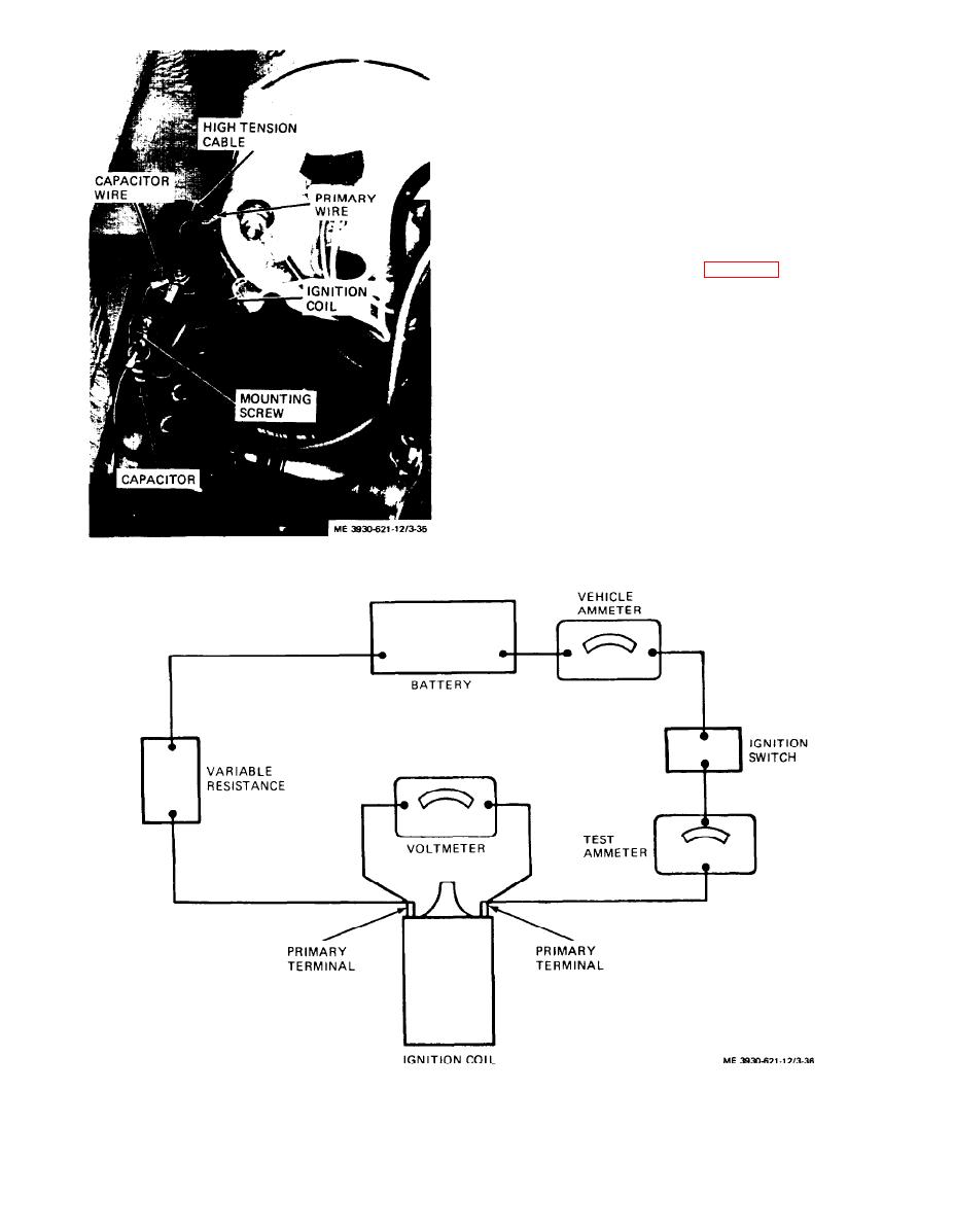 (1) A test ammeter is required as shown to give
accurate measurement.
(2) Close ignition switch and adjust voltage to 12
volts.
(3) Test ammeter should read 2 to 3 amperes.
(4) Remove connections and instruments used
for test wiring.
e. Primary Ignition Circuit Resistance Test. Con-
nect a voltmeter with a one volt scale in series with
the positive battery terminal and the coil primary
terminal opposite distributor primary terminal.
(1) Remove distributor cap (para 3-44) and rotate
engine to close breaker points in distributor.
(2) Turn ignition switch to ON position. Volt-
meter should not read more than 0.20 volts.
(3) Turn ignition switch to OFF position. Dis-
connect voltmeter leads from battery and coil. Con-
nect one voltmeter lead to coil primary connected to
distributor and ground the other to the distributor
housing.
(4) Turn ignition switch to ON position. Volt-
meter should read less than 0.10 volts.
(5) If readings exceed the values specified, re-
place ignition coil.
(6) Turn ignition switch to OFF position and
disconnect test circuit.
Figure 3-35. Ignition coil, installed view.
Figure 3-36. Ignition coil test wiring.
3-34
|
|
Privacy Statement - Press Release - Copyright Information. - Contact Us |
