 |
|||
|
|
|||
|
Page Title:
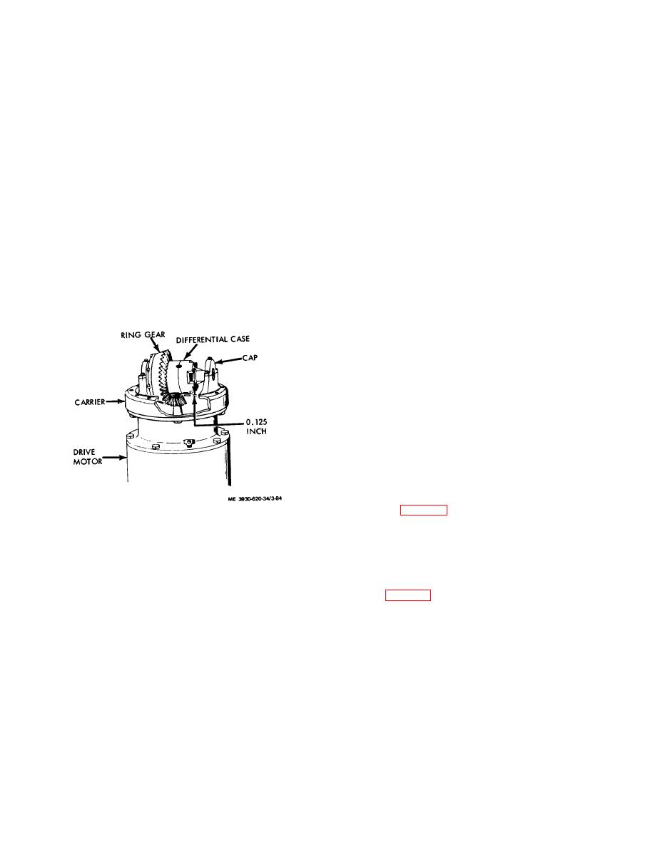
Figure 3-84. Measuring for shims. |
|
||
| ||||||||||
|
|
 taking care that bar stock is flat on face of pinion gear
7. Install the required shims and reinstall
and does not ride on the shaft.
differential assembly on carrier.
4. Using a feeler gauge, measure the
8. Install caps and secure with screws.
remaining distance between bar stock and outside
9. Using a dial indicator, check ring gear
diameter of differential case.
laterally for backlash at four position (90 degrees apart).
5. Add the thickness of bar stock and feeler
Backlash should be 0.005 and 0.010 inch.
gauge measurement. The total measurement will be
Caution: When adjusting backlash, rotate
referred to as sum A.
each adjusting nut exactly the same distance to
Note. A measurement is etched on the pinion
maintain proper bearing preload.
gear and ring gear. Insure both measurements are
10. Backlash is increased by removing lock,
identical, then record the measurement.
loosening adjusting nut nearest ring gear, and tightening
6. If measurement is a + (plus), then add it to
opposite nut.
0.156 inch.
11. Backlash is decreased by removing lock,
7. If measurement is a (minus), then subtract
loosening adjusting nut farthest from ring gear, and
it from 0.156 inch.
tightening opposite nut.
8. The result obtained in step 6 or 7 will be
(17) The remaining reassembly and installation is
referred to as sum B.
in the reverse order of disassembly.
9. Subtract sum A from sum B.
The
(18) Attach motor and carrier to drive axle housing.
difference is the thickness of shims required between
(19) Install drive unit assembly in lift truck.
carrier housing and drive motor housing.
(20) Install drive wheels.
10. Measure and install the required shims on
(21) Install mast assembly and attach forks.
the drive motor.
(22) Connect all lines, hoses, cables, etc.
11. Reinstall and secure the carrier.
(23) Replace fluids in differential and hydraulic oil
reservoir (LO 10-3930-620-12).
(24) Bleed brake system (TM 10-3930-620121.
3-48. Drive Motor
a. General. The drive motor is a dc series wound,
flange mounted type. A replaceable armature shaft is
employed, mounted on a sealed bearing at the
commutator end and a double row thrust bearing at the
drive end. Dual metal graphite brushes are supported in
fixed, box type holders to assure proper brush alignment.
A metal clip on top of each brush forms a stop device
that prevents commutator scoring.
b. Brush and Brushholder Service. Brushes can be
replaced without removing the drive motor from the
truck, as follows:
(1) Disconnect
battery
and
discharge
capactiors (para 2-5).
Figure 3-84. Measuring for shims.
(2) Remove the toe and the floor plates (TM
(b) Differential case removed from carrier.
10-3930-620-12).
1. Remove screws securing carrier caps and
(3) Remove the rear cover from around the
remove caps.
stator.
2. Remove differential assembly from carrier.
(4) Remove brush retaining screws, lift brush
3. Place a flat piece of 1.2220 inch thick bar
retaining springs, and withdraw brushes from brush
stock on the pinion gear of the motor.
holder. (fig. 3-85)
Note. Bottom side should be drilled out so
Note. Before new brushes are installed. they
that armature shaft does not prevent bar from lying
should be contoured on a sanding drum with the
flat.
same diameter as the commutator. Hold brushes to
4. Place a piece of round bar stock
sanding drum to obtain the same radius and brush
approximately 7 1/ 4 inches long by 3.142 inches
angle on contact face as was on old brushes. Final
diameter across carrier.
seating can be maintained with a fine mesh seating
5. Measure distance between bar stock and
stone while conmmutatior is turning.
add amount etched on pinion gear.
6. Subtract measurement obtained in step 5.
from 0.040. inch to obtain total measurement of
required shims.
3-95
|
|
Privacy Statement - Press Release - Copyright Information. - Contact Us |
