 |
|||
|
|
|||
|
Page Title:
Figure 3-83. Differential. Exploded view. |
|
||
| ||||||||||
|
|
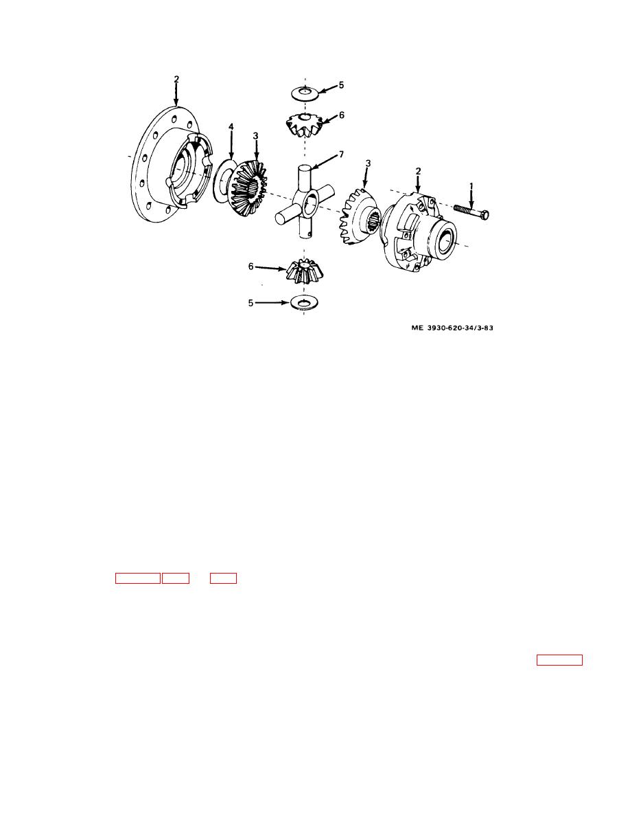 1.
Screw
2.
Case assembly
3.
Side gear
4.
Spacer
5.
Spacer
6.
Pinion
7.
Shaft
Figure 3-83. Differential. Exploded view.
d. Cleaning and Inspection.
(9) Install differential bearings, adjusting
nuts, bearing caps, and screws. Do not fully tighten
screws.
Note. Ring gear and pinion shall be replaced
(10) Loosen adjusting nut at ring gear end by
as a set. Thrust washers shall be replaced as matching
rotating adjusting nut to the right as far as possible and
sets.
pulling ring gear up tight against adjusting nut.
(11) Tighten adjusting nut opposite ring gear by
(1) all parts for excessive wear, damaged, or
rotating adjusting nut to the right as far as possible.
broken parts. Spacers shall be 1 / 32 inch, minimum.
(12) Wrap a cord around the differential case
(2) excessively worn, damaged, or broken
and attach a spring scale to the loose end.
parts.
(13) Gradually pull on the scale and note the
e. Reassembly. (fig. 3-81, 3-82, and 3-83.)
effort required to rotate case.
(1) Install groove pins in ring gear.
(14) Check that case starts and maintains
(2) Install ring gear by drawing up gear using
rotation at less than 3 pounds of pull.
special mounting screws.
(15) Install carrier assembly on drive motor but
(3) Lockwire screws in position.
do not install shims.
(4) Assemble spider pinion gears, thrust
(16) Measuring for Shims.
washers. and side gear on spider.
(a) Differential case installed in carrier. (fig. 3-84.)
Note. Insure that alignment marks on case
1. Obtain a flat piece of bar stock
halves are matched.
approximately O.1.25 inch thickness.
(5) Install spider assembly into differential
2. Measure and record the exact
case.
thickness of the bar stock in thousandths of an inch.
(6) Install and tighten screws on case.
3. Place bar stock on face of pinion
(7) Lockwire screws in position.
gear,
(8) Place differential case in carrier.
Caution: Ensure that markings on caps
and housing are
matched before installing caps.
3-94
|
|
Privacy Statement - Press Release - Copyright Information. - Contact Us |
