 |
|||
|
|
|||
|
Page Title:
Section V. DRIVE AXLE, BRAKE ASSEMBLY AND DIFFERENTIAL |
|
||
| ||||||||||
|
|
 TM 10-3930-611-35
1.
Bolt, wheel (10 reqd)
20.
Pin, king (2 reqd)
2.
Wheel (2 reqd)
21.
Bearing, thrust (2 reqd)
3.
Tire (2 reqd)
22.
Washer, thrust (2 reqd)
4.
Screw, flat head (8 reqd)
23.
Spindle, RH
5.
Cover, hub (2 reqd)
24.
Spindle, LH
6.
Pin, cotter (2 reqd)
25.
Fitting, hub (4 reqd)
7.
Nut, slotted hex (2 reqd)
26.
Nut, lock (6 reqd)
8.
Washer, flat (2 reqd)
27.
Bolt, close tolerance (6 reqd)
9.
Weldment, hub (2 reqd)
28.
Weldment, articulating axle
10.
Cone, outer roller brg (2 reqd)
29.
Joint, ball (4 reqd)
11.
Seal (2 reqd)
30.
Nut, jam (4 reqd)
12.
Cone, inner roller brg (2 reqd)
31.
Tube (2 reqd)
13.
Cup, inner roller brg (2 reqd)
32.
Fitting, lub (4 reqd)
14.
Cup, outer roller brg (2 reqd)
33.
Arm, lever
15.
Pin, cotter (4 reqd)
34.
Key
16.
Nut, slotted hex (4 reqd)
35.
Crank, bell
17.
Washer, flat (4 reqd)
36.
Bearing (2 reqd)
18.
Screw, set, cup point (2 reqd)
37.
Housing, bearing
19.
Bearing, needle (4 reqd)
38.
Fitting, lub (ref item #32)
Figure 3-24. Steering axle assembly, disassembly and reassembly.
Section V. DRIVE AXLE, BRAKE ASSEMBLY AND DIFFERENTIAL
3-20. General
This section provides information useful in the
maintenance and repair of the drive axle, brake
assembly, and differential of the forklift truck.
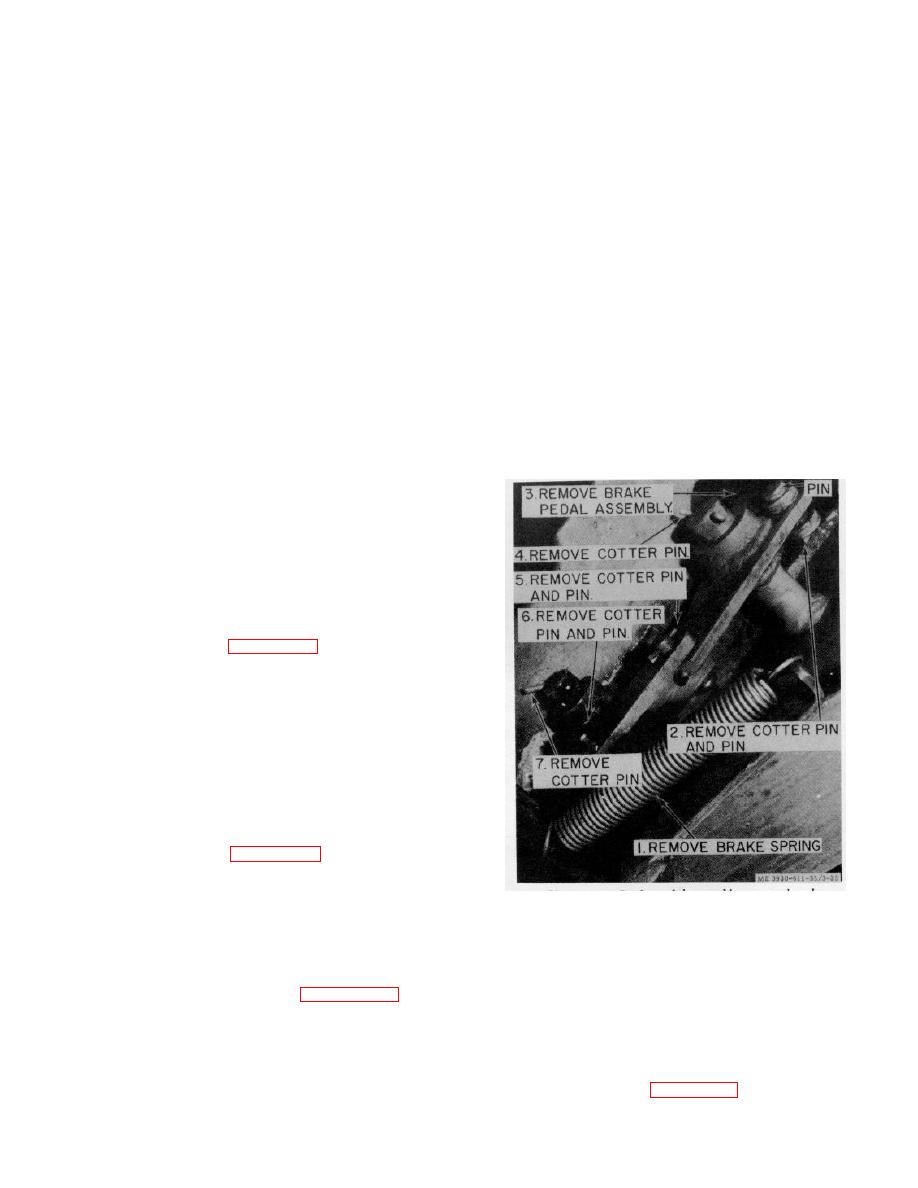
3-21. Brake Pedal Assembly
a. Removal.
(1) Remove the front and rear floor plates
and brake master cylinder (TM 10-3930-611-12).
(2) Refer to figure 3-25 and remove the
service brake pedal.
b. Cleaning and Inspection.
(1) Clean all parts with dry cleaning
solvent (Federal Specification P-D-680) and dry
thoroughly.
(2) Inspect for breaks, cracks, bends,
loose or missing mounting hardware, or other defects.
(3) Tighten or replace loose or missing
mounting hardware, replace a damaged or defective
part as necessary.
c. Installation.
(1) Refer to figure 3-25 and install the
service brake pedal.
(2) Install the brake master cylinder and
Figure 3-25. Brake pedal assembly, removal and
the front and rear floor plates (TM 10-3930-611-12).
installation.
c. Cleaning and Inspection.
3-22. Brake Master Cylinder
(1) Clean all parts with dry cleaning
a. Removal.
Remove the brake master
solvent (Federal Specification P-D-680) and dry
cylinder (TM 10-3930-611-12).
thoroughly.
(2) Inspect for deteriorated cups or cuts in
disassemble the brake master cylinder.
lip of cups. Inspect for breaks, cracks, deteriorated
seals, or other defects.
(3) Replace deteriorated or cut cups and
other damaged or defective parts as necessary.
d. Reassembly. Refer to figure 3-26 and reassemble
3-31
|
|
Privacy Statement - Press Release - Copyright Information. - Contact Us |
