 |
|||
|
|
|||
|
|
|||
| ||||||||||
|
|
 TM 10-3930-611-35
CHAPTER 3
REPAIR INSTRUCTIONS
Section I. ELECTRICAL SYSTEM
3-1. General
core. If a grounded armature coil is evidenced, replace
the armature.
This section provides information useful in the
f.
Reassembly.
Refer to figure 3-3 and
repair of the forklift electrical system. The electrical
reassemble the hydraulic pump motor.
system consists of a drive motor, hydraulic pump motor,
g. Pump Coupling Chain Reassembly and
wiring, and various other components which assure the
proper operation of the truck.
chain.
3-2. Hydraulic Pump Motor
the hydraulic pump and the hydraulic pump motor as an
assembly.
the hydraulic pump and the hydraulic pump motor as an
assembly.
b. Pump Coupling Chain Removal and
coupling chain.
c. Disassembly.
Refer to figure 3-3 and
disassemble the hydraulic pump motor.
d. Cleaning, Inspection and Repair.
(1) Wipe all electrical parts with a clean,
dry cloth. Clean all other parts with dry cleaning solvent
(Federal Specification P-D-680) and dry thoroughly.
(2) Inspect all wires and terminals for
breaks and corrosion. Inspect brushes for amount of
wear and evidence of chipping. Inspect brush holders
for proper spring tension (2.5 lbs.). Inspect commutator
for burns and high mica. Inspect chain and sprocket,
and other parts for breaks, cracks, dents, loose or
missing mounting hardware, or other defects.
(3) Clean corrosion from wires and
electrical connections, tighten or replace loose or
missing hardware. Replace a damaged or worn chain or
sprocket. If necessary, undercut commutator mica to a
depth equal to the thickness of the mica and take a light
cut from the commutator in a lathe. If brushes are
shorter than 13/16 inch, replace and sand in as
necessary. Replace damaged parts.
the probes to each end of the field coil terminals to test
for continuity. Test for grounded field coils by touching
one probe to the field coil circuit and the other to the
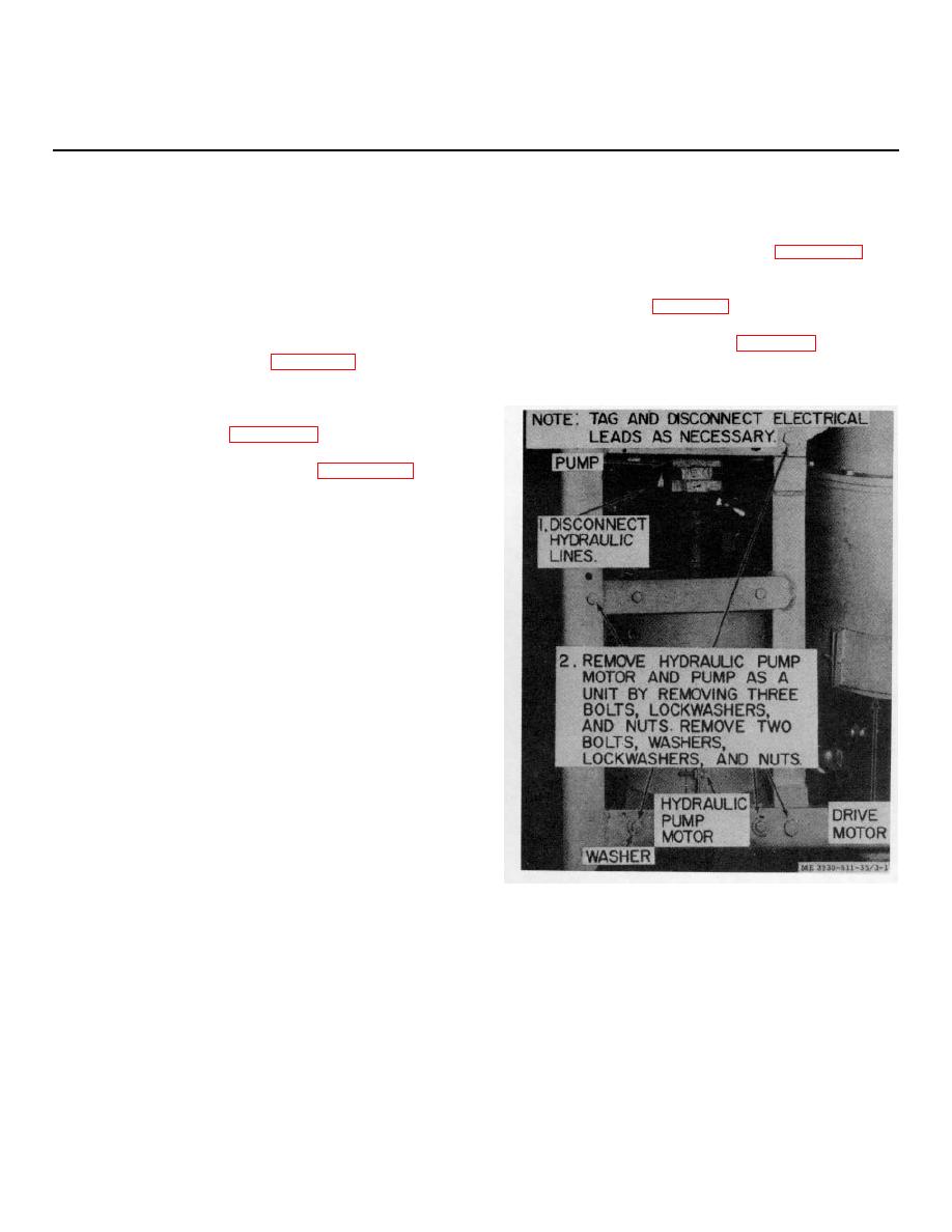
Figure 3-1. Hydraulic pump and hydraulic pump motor,
field core frame. If lack of circuit continuity or grounded
removal and installation.
coil is indicated, replace the field coils. Touch one test
probe to the commutator and the other to the armature
3-1
|
|
Privacy Statement - Press Release - Copyright Information. - Contact Us |
