 |
|||
|
|
|||
|
Page Title:
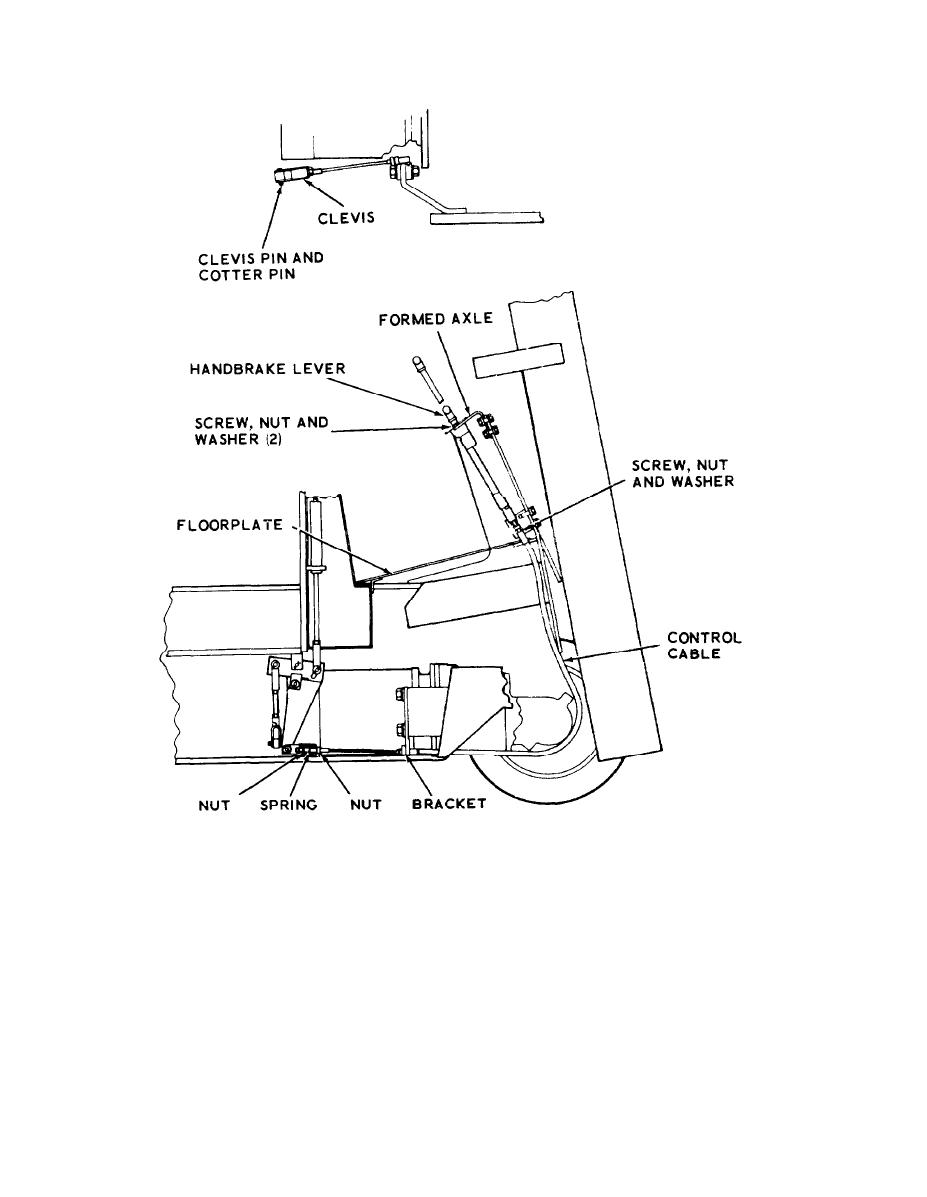
Figure 3-6. Handbrake lever, cable and control linkage. |
|
||
| ||||||||||
|
|
 TM 10-3930-609-12
ME 3930-609-12/3-6
Figure 3-6. Handbrake lever, cable and control linkage.
hose in clean container partially filled with hy-
(4) Maintain fluid level in master cylinder
draulic brake fluid. Be sure end of hose is sub-
and continue to operate brake pedal until fluid
merged in the hydraulic fluid.
flows in a steady solid stream without air bub-
(3) Turn bleeder screw counterclockwise
bles. Close bleeder screw by turning it clock-
three-quarters of a turn. Apply steady pressure
wise. Remove bleeder hose, and replace small
to brake pedal. Hydraulic fluid containing air
screw in bleeder screw.
bubbles should be forced through bleeder hose
(5) Repeat bleeding procedure at other
into container.
wheel, replenishing brake fluid in master cy-
3-15
|
|
Privacy Statement - Press Release - Copyright Information. - Contact Us |
