 |
|||
|
|
|||
|
|
|||
| ||||||||||
|
|
 HYDRAULIC
6. Slide cover over gear shafts, being careful not
4. Secure pump and adapter to the timing gear
to damage O-rings, and make sure that the seal ring is
case. Observe the alignment between mounting bore,
in position when flange makes contact with pump body.
adapter and pump frequently to avoid binding of
Secure mounting flange to body.
components. Tighten each mounting bolt alternately
and torque evenly.
7. Insert relief valve ball into body, tap lightly with
a brass drift and light hammer to insure seating. Install
5. Replace hydraulic hoses and tighten sufficiently
spring and cap.
to eliminate pressure and vacuum leaks.
F. INSTALLATION
6. Be sure no load is imposed on the hydraulic
system, then prime the pump. When pump is primed
1. Flood pump with oil to remove any foreign
and the system is charged, check the pressure relief
particles and insure lubrication.
setting, adjust if necessary.
G. BREAK-IN PROCEDURE
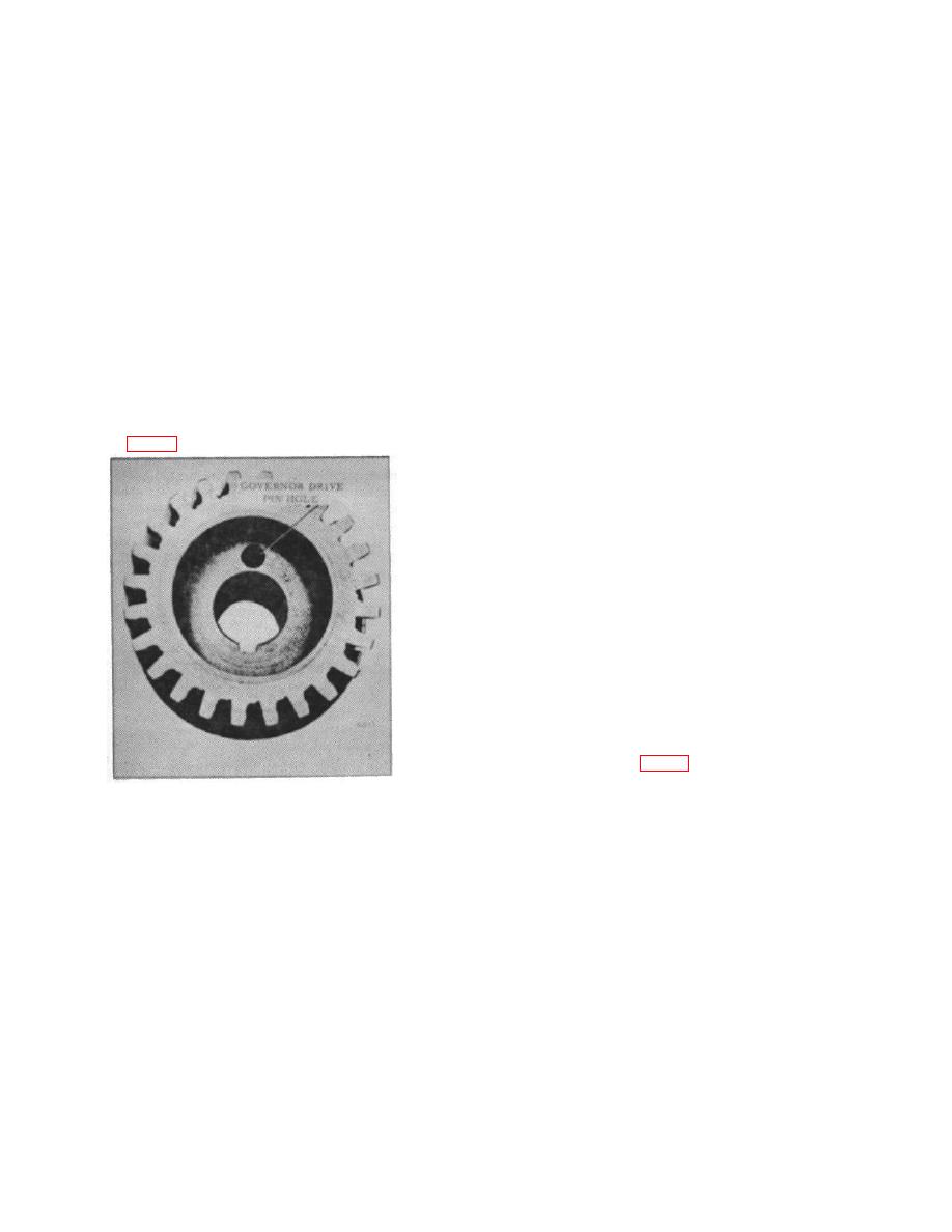
2. Place new gasket and O-ring on the adapter.
Place adapter in its mounting bore on the engine. Be
sure the governor drive pin is in the pump gear governor
1. Break-in will be required for new pumps, rebuilt
pin hold. (Fig. 6)
pumps, or those out of service for an extended time.
2. Prime pump: Fill suction hose with correct
hydraulic oil. Pour oil in suction and discharge pump
ports before securing hoses. Due to position and/or
location, complete filling of suction hose may be
impossible, so fill to permissible limit.
3. Start engine and run at 1000 RPM until pump
picks up prime. Prime pick-up may be checked by
activating control lever. Run engine at 1000 RPM for 10
minutes after prime pick-up.
MANUAL CONTROL VALVE
A. GENERAL
The Control Valve (Fig. 7) consists of a one piece body,
operating spools, two check valves for each spool, an
Figure 6.
adjustable relief valve and the necessary seals and
plugs.
3. Place a new gasket on pump and work pump
into a position near the adapter. Align pump drive key
The body is constructed of a one piece casting, cored to
with the keyway in the adapter gear bore. Push pump
contain passages for a full series parallel circuit. Cored
shaft into the adapter bore being careful not to lose the
body outlet ports are machined for removable SAE O-
drive key.
ring fittings.
B-148
|
|
Privacy Statement - Press Release - Copyright Information. - Contact Us |
