 |
|||
|
|
|||
|
|
|||
| ||||||||||
|
|
 ELECTRICAL
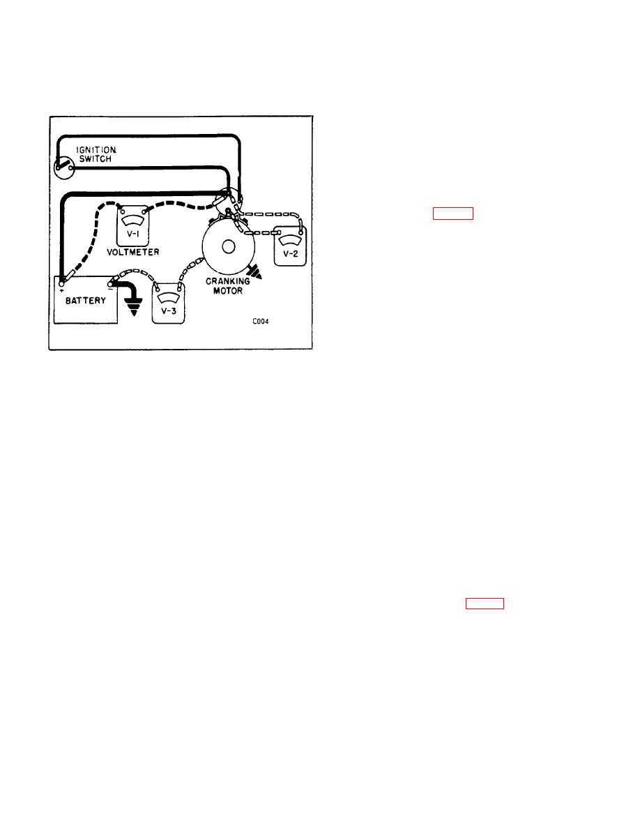
and V-3 (with voltmeter connected to the negative (-)
D. REMOVAL
battery post and the starter field frame).
1. Disconnect: the battery ground cable from the
battery; the cable from the cranking motor, solenoid or
magnetic switch; the wires from the solenoid or
magnetic switch.
2. Remove the two capscrews holding the motor to
the flywheel housing. Lift the motor toward the rear of
the truck.
E. DISASSEMBLY (Fig. 31)
NOTE: Normally, the cranking motor
should be dismantled only to the
point where repair or replacement of
parts can be made. However, the
cranking
motor
should
be
disassembled completely at regular
intervals for the cleaning and
inspection of all parts.
1. Remove screw and lock washer attaching field
Figure 32.
coil connector strap to lower terminal on solenoid.
2. If V-1, V-2, or V-3 exceeds 0.5 volt, excessive
2. Remove through-bolts attaching commutator end
resistance is indicated in that part of the circuit being
frame and field frame to drive end housing. Remove
checked. Locate and eliminate the cause for any
commutator end frame.
excessive voltage drop in these circuits in order to
obtain maximum efficiency from the starting system.
3. Remove field frame from armature and drive-
housing.
3. If starter fails to crank engine, first make sure
battery is not discharged, then check solenoid operation.
4. Remove armature and drive assembly from drive
If solenoid plunger fails to pull in, the trouble may be
housing, tilting armature as necessary to disengage lugs
due to excessive resistance in the solenoid control
on shift lever from drive collar.
circuit. Check all wiring and connections from ignition
switch to solenoid for loose or corroded connections.
5. Remove two screws and lock washers attaching
solenoid to drive housing. Remove solenoid and return
4. If cause of excessive resistance is not apparent,
spring from drive housing and plunger.
connect a short jumper lead across the solenoid
"battery" and "S" terminals. If solenoid plunger pulls in,
6. Remove over-running clutch drive assembly
trouble is in solenoid control circuit. Check for defective
from armature shaft as follows:
ignition switch. If solenoid plunger does not pull in with
jumper lead connected, solenoid is defective and must
a. Slide thrust collar (Fig. 33) off end of armature
be replaced.
shaft.
B-75
|
|
Privacy Statement - Press Release - Copyright Information. - Contact Us |
