 |
|||
|
|
|||
|
|
|||
| ||||||||||
|
|
 ELECTRICAL
(1) A shorted battery cell.
Starter pinion is shifted into mesh with wheel ring gear
teeth and starter circuit is completed by the solenoid
(2) A high voltage regulator setting.
when the solenoid is energized by the key starting-
ignition switch, Primary circuit to ignition coil is also fed
1. Shorted Battery Cell: Checks for shorted battery
from the solenoid while the starter is operating.
cells should be made as this can cause the battery to be
overcharged.
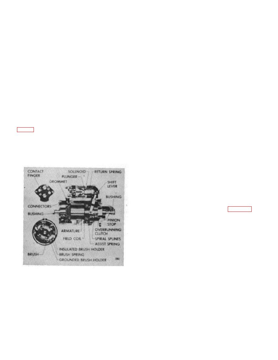
The drive end housing is extended to enclose the entire
shift lever mechanism and solenoid plunger. The
2. High Voltage Regulator Setting: If no circuit
solenoid flange is mounted on the drive end housing,
defects are found, yet the battery remains overcharged,
with sealing compound used between flange and field
the cause is probably a high voltage regulator setting.
frame. The shift lever return spring is a compression
type spring located inside the solenoid case. A special
assist spring is located around the armature and the
CRANKING MOTOR
collar of the clutch drive. This assist spring aids the
solenoid in overcoming the return spring force in the first
A. GENERAL
movement of the clutch along the armature shaft.
The 12 volt cranking motor is a 4 pole, 4 field coil unit
B. PERIODIC MAINTENANCE
that has the solenoid, solenoid plunger, and solenoid
shift lever mechanism enclosed in the drive housing.
No periodic lubrication of the cranking motor solenoid is
required. The cranking motor and brushes can be
drive is used to engage the cranking motor pinion with
inspected only when the unit is disassembled, so no
the flywheel. The armature shaft and clutch have
service is necessary between overhaul periods.
mating spiral spines that prevent transfer of full cranking
power until the pinion is fully engaged with the flywheel
C. STARTING CIRCUIT TESTS
ring gear.
NOTE: The following tests are for
solenoid
equipment
cranking
motors. However, they can be used
as guides to check the starting
circuits
of
cranking
motors
controlled by magnetic switches.
1. Disconnect the primary lead to the distributor to
prevent engine starting. Referring to Figure 32, and
with starter cranking engine during each check, measure
V-1 (with voltmeter connected to the positive (+) battery
post and the solenoid battery terminal), V-2 (with
voltmeter connected to the solenoid battery terminal and
solenoid motor terminal),
Figure 31.
B-74
|
|
Privacy Statement - Press Release - Copyright Information. - Contact Us |
