 |
|||
|
|
|||
|
|
|||
| ||||||||||
|
|
 ELECTRICAL
8. Install the springs and brushes into the brush
holder, and insert a straight wire or pin into the holes at
the bottom of the holder to retain the brushes. (Fig. 10)
Then attach the brush holder assembly onto the end
frame, noting carefully the proper stack-up of parts as
shown in Figure 10. Allow the straight wire to protrude
through the hole in the end frame.
9. Assemble the heat sink onto the slip ring end
frame. (Fig. 15)
Figure 16.
H. INSPECTION
The frequency of inspection is determined largely by the
type of operating conditions. High speed operation, high
temperatures, and dust and dirt all increase the wear of
brushes, slip rings and bearings.
Figure 15.
At regular intervals, inspect the terminals for corrosion
10. Remove the tape over the slip ring end frame
and lose connections, and the wiring for frayed
bearing and slip ring end of the rotor shaft. Make sure
insulation. Chock the mounting bolts for tightness, and
the shaft is clean.
the belt for alignment, proper tension and wear. When
tightening belt tension, apply pressure against the stator
11. Slide the slip ring end frame over the rotor
laminations between the end frames, and not against
shaft. Align the scribe marks previously made. Secure
either end frame.
the assembly with the through bolts, tightening them
alternately and evenly.
I. INSTALLATION
12. Withdraw the wires or pins holding the brushes
1. Position alternator at mounting bracket and
of the slip rings. Check the output of the alternator.
install mounting bolts, nuts, and lock washers.
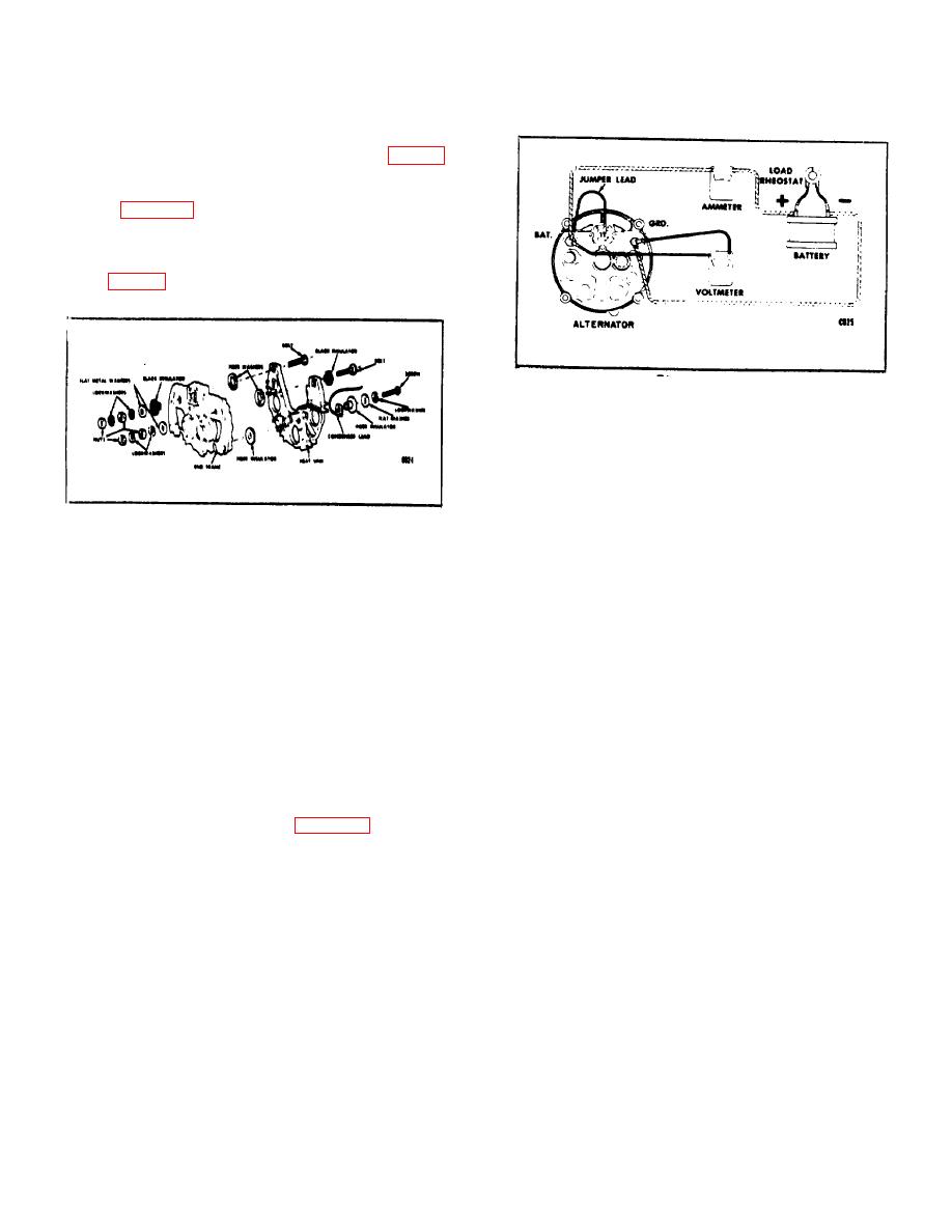
G. OUTPUT CHECK
2. Place belt in alternator pulley, then attach
adjusting arm to alternator drive end frame with cap
1. Check the alternator on a test bench, make
screw and washers. Adjust belt tension then tighten
electrical connections as shown in Figure 16, operate at
adjusting arm cap screw and mounting bolts.
specified speed, and check for rated output.
3.
Connect wires to generator according to
2. Adjust the load rheostat, if necessary, to obtain
identification made at time of removal, or by referring
the desired output.
to the wiring diagram. Make sure connections are tight,
NOTE: Connect the negative battery
post to the alternator frame.
B-64
|
|
Privacy Statement - Press Release - Copyright Information. - Contact Us |
