 |
|||
|
|
|||
|
|
|||
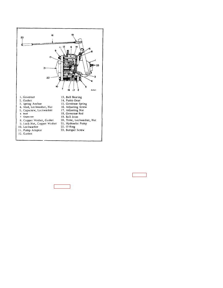
| ||||||||||
|
|
 ENGINE
are "in", that is, in the bottom of the driver slots, the
space between the top of the conical shaped race
bushing and hair pin clip should be .230" - .240". Use
.010" spacer washers to obtain required space. The
governor shaft is pressed into the gear and secured with
a screw that is partially in the shaft and partially in the
gear.
ASSEMBLY
1. When reassembling pistons and connecting
rods, use a good ring compressor and oil the bores
thoroughly. A hammer handle may be used to tap the
pistons out of the ring compressor into the cylinder bore.
2. Use care to prevent damage to cylinder bore
finish by the connecting rods when the connecting rods
are assembled over the crank pin.
Locate them
carefully to prevent damage to the bearing surface, and
crankshaft journals.
3. Always lubricate the bearings with clean engine
oil when assembling. Tighten the bearings to specified
torque. Use lockwires as required to prevent loosening
of nuts and screws.
4. Clean the cylinder head and block surfaces
thoroughly before installing the gasket.
Tighten all cylinder head capscrews evenly and in
Figure 62
specified sequence. Torque to specification.
Turning the nuts clockwise increases the spring tension
5. Make certain the gasket surfaces are flat and
thus raising the engine speed.
clean, before assembling the oil pan with new gaskets.
Turning the nuts counterclockwise decreases the spring
Tighten screws in accordance with specified limits.
tension. After making the adjustment, be sure to tighten
When engine is assembled and filled with proper oil, set
the two locknuts.
tappets. (Fig. 63) See Specification Listing.
5. Should governor surge at no-load high idle,
INSTALLATION
screw bumper screw (Fig.
eliminated. Do not run bumper screw in far enough to
After engine is placed in the chassis and major
increase speed.
components are installed, perform the following:
C.
SERVICE
The driver must always be tight to the shaft.
The races must be free on the shaft. In assembly of the
governor a space of .004" to .006" is provided between
the driver and the flat race. This is to assure freedom
for movement of the flat race. When servicing the
governor, make sure that both races revolve freely on
the
shaft.
When
the
balls
B-22
|
|
Privacy Statement - Press Release - Copyright Information. - Contact Us |
