 |
|||
|
|
|||
|
Page Title:
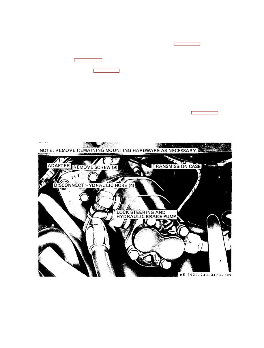
Lock Steering and Hydraulic Brake Pump |
|
||
| ||||||||||
|
|
 ( 4 ) Inspect coupling and adapter for damage.
e. Reassemble.
a. General. The lock steering and hydraulic
(1) Lubricate each part with clean, SAE No.
brake pump is mounted to the transmission. The
10 oil.
pump is a dual pump. One portion of the pump
( 2 ) Refer to figure 3-110 and reassemble the
supplies hydraulic pressure to the lock steering
l o c k steering and hydraulic brake pump assembly.
cylinders and the other portion of the pump fur-
(3) Tighten the screws that secure front and
nishes hydraulic pressure to the brakes.
r e a r covers to the housing to 28 to 32 foot-pounds
b. R e m o v a l . R e f e r t o f i g u r e 3 - 1 0 9 a n d r e m o v e
the lock steering and hydraulic brake pump.
NOTE
disassemble the lock steering and hydraulic brake
After overhaul, run pump for 30 minutes at 2000
rpm while pumping SAE No. 10 oil at 0 psi outlet
pump as follows:
pressure.
(1) Scribe a match mark on body front (31)
and rear (1) covers to insure that pump will be
f. Test. B e n c h - t e s t p u m p b y d r i v i n g i t a t 2 8 0 0
r e a s s e m b l e d in exactly the same manner as it was
r p m and load pump to 1600 psi. Pump capacities
before disassembly.
are: large, 35 Gallons Per Minute, and small, 15
(2) Disassemble in numerical sequence.
gallons per minute.
d. Inspection.
( 1 ) Inspect gears for broken or damaged teeth.
l o c k steering and hydraulic brake pump assembly.
(2) Inspect bearing for excessive wear.
( 3 ) Inspect housing and covers for cracks and
damage.
removal and installation.
|
|
Privacy Statement - Press Release - Copyright Information. - Contact Us |
