 |
|||
|
|
|||
|
Page Title:
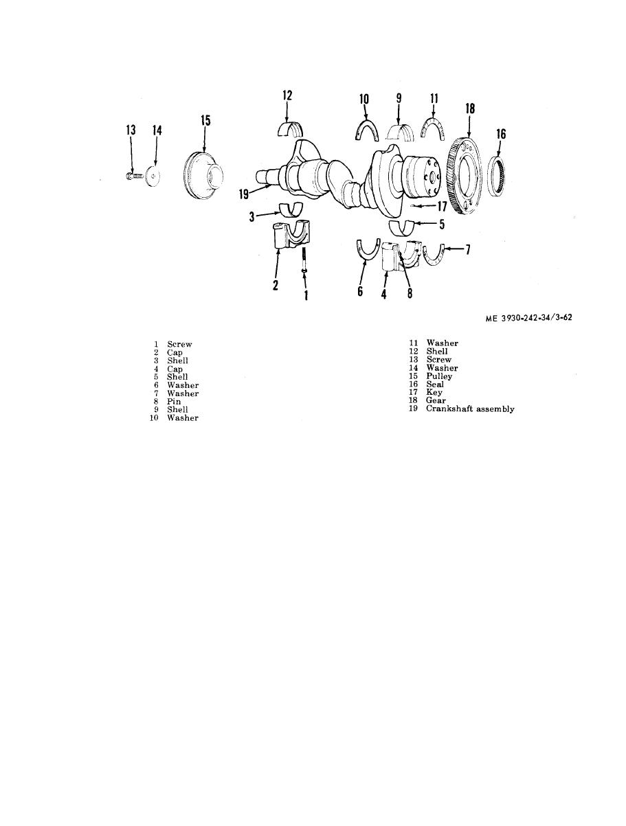
Figure 3-62. Crankshqft, removal and installation |
|
||
| ||||||||||
|
|
 TM 10-3930-242-34
installation.
(9) Check the lube oil pump drive gear and
s h a f t . Otherwise, it may be necessary to use
crankshaft timing gear for worn or chipped
0 . 0 0 5 inch oversize rear thrust washers.
t e e t h and replace if necessary.
( 7 ) Inspect keyways for evidence of cracks
(10) If the crankshaft is worn so that the
o r worn condition, and replace shaft if neces-
connecting rod or main bearing maximum
sary.
journal-to-bearing shell clearance (with new
( 8 ) Carefully inspect crankshaft in the area
s h e l l s ) exceeds 0.0044 inch and 0.0046 inch, or
of the front and rear oil seal contact surface for
t h e maximum journals taper or out-of-round is
evidence of rough or grooved condition. Any im-
g r e a t e r than 0.003 inch, the crankshaft must be
perfections of oil seal contact surface will result
replaced. M e a s u r e m e n t s o f t h e c r a n k s h a f t
in oil leakage at this point.
s h o u l d be accurate to the nearest 0.002 inch.
NOTE
d. Installation.
Slight ridges of approximately 0.0002 inch in vari-
(1) Install upper grooved bearing shells in
ation may be removed with crocus cloth, wet with
t h e cylinder block.
fuel oil. The crankshaft should be rotated at in-
( 2 ) Apply clean engine oil to all crankshaft
t e r v a l s to remove ridges from the complete cir-
c u m f e r e n c e of the shaft without disturbing the
j o u r n a l s and set crankshaft in place.
concentricity. Ridges which approach 0.0005 inch
(3) Install the upper halves of the rear main
or greater should first be cleaned up with 120 grit
bearing thrust washers on each side of the bear-
emery cloth, followed by use of 240 grit emery
i n g , and the doweled lower halves on each side
cloth for finishing. Crocus cloth, wet with fuel oil,
o f the rear main bearing cap.
should then be used for final polishing. If exces-
sive wear or grooving is present, and cannot be
( 4 ) With the lower main bearing shells in-
cleaned up satisfactorily, the oil seal may be pres-
stalled in bearing caps, tap the caps lightly with
sed in the flywheel housing and front cover ap-
a soft hammer to seat them properly and draw
proximately 1/8 inch from its original position.
|
|
Privacy Statement - Press Release - Copyright Information. - Contact Us |
