 |
|||
|
|
|||
|
Page Title:
Fuel Injector Control Lever and Tube Assembly |
|
||
| ||||||||||
|
|
 TM 10-3930-242-34
FUEL SYSTEM
Section II.
3-12. General
s e m b l e fuel injector control lever and tube as-
The engine fuel system consists of the fuel
sembly.
injectors, fuel pump, and fuel tank. A restricted
f. Installation and adjustment.
f i t t i n g is located in the cylinder head to main-
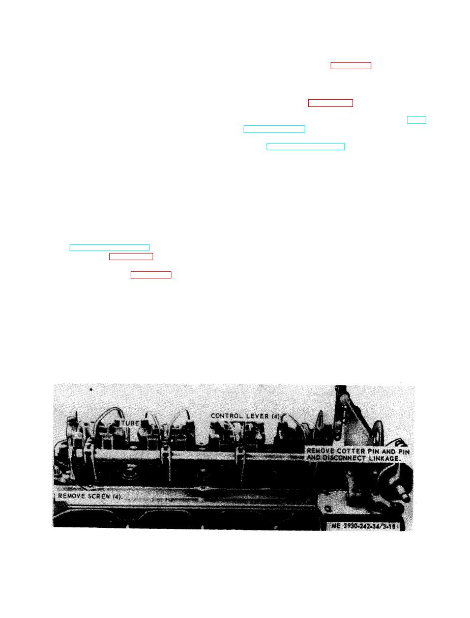
(1) Refer to figure 3-18 and install the fuel
tain pressure in the fuel system. There are
i n j e c t o r control lever and tube assembly.
three rocker arms and three push rods for each
(2)
Adjust
the
control
levers
(TM
c y l i n d e r . One rocker arm operates the fuel in-
10-3930-242-12).
j e c t o r plunger; the other two operate the ex-
(3) Install the rocker arm cover and engine
h a u s t valves.
hood (TM 10-3930-242-12).
3-13. Fuel Injector Control Lever and Tube
Assembly
a. General.
a. General. Each fuel injector is actuated by a
(1) The unit fuel injector performs four
lever on the injector control tube, which in turn,
functions:
is connected to the governor by means of a fuel
( a ) C r e a t e s t h e h i g h f u e l p r e s s u r e re-
rod, These levers can be adjusted independently
q u i r e d for efficient injection,
o n the control tube, thus permitting a uniform
(b) Meters and injects the fuel in t h e
setting of all injector racks.
e x a c t amount required to handle the load,
b. Removal,
(c) Atomizes the fuel for mixing with t h e
(1) Remove the engine hood and rocker arm
a i r in the combustion chamber.
cover (TM 10-3930-242-12).
(d) Permits continuous fuel flow,
(2) Refer to figure 3-18 and remove the fuel
( 2 ) Each fuel injector has a circular disc
i n j e c t o r control lever and tube assembly,
p r e s s e d into a recess at front side of injector
body for identification purposes. The identifica-
assemble the fuel injector control lever and tube
tion tag indicates the nominal output of injector
assembly,
i n cubic millimeters. A horizontal bar on the
d . Cleaning and Inspection.
i n j e c t o r identification tag between the "GM"
(1) Clean fuel injector control levers and
a n d the injector size identifies needle valve.
tube, using a cleaning solvent such as P-D-680,
or equal,
CAUTION
(2) Inspect the levers for cracks.
Do not intermix needle valve injectors
(3) Inspect the tube assembly for dents and
with other types of injectors in an engine.
breaks.
( 4 ) Inspect all hardware for damage. Re-
(3) Fuel in excess of that required for en-
p l a c e a defective part.
g i n e operation is circulated through the injec-
Figure 3-18. Fuel injector control lever and tube assembly,
removal and installation.
|
|
Privacy Statement - Press Release - Copyright Information. - Contact Us |
