 |
|||
|
|
|||
|
|
|||
| ||||||||||
|
|
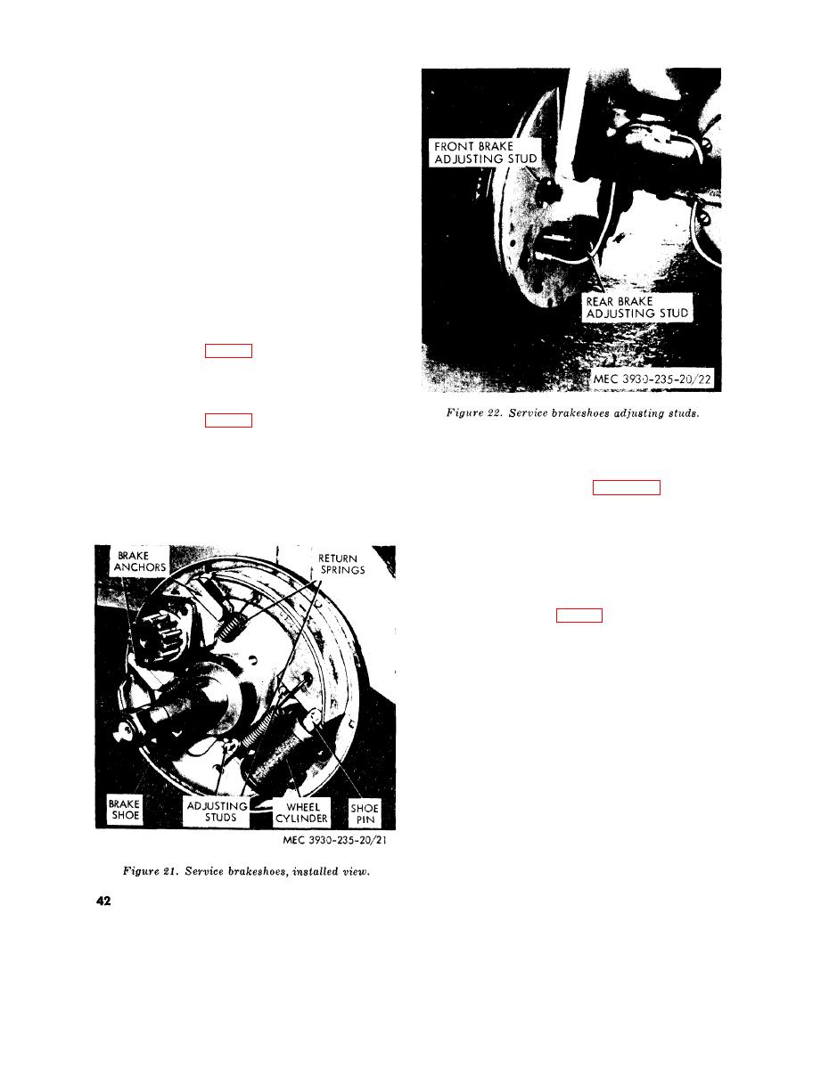 51. Service Brake Brakeshoes
a. Adjustment. Each brakeshoe may be ad-
justed by turning an adjusting stud, mounted
on the backing plate. This adjustment compen-
sates for normal lining wear. The opposite end
of brakeshoe slides back and forth in the anchor
slot and requires no adjustment. To adjust
brakes, turn adjusting stud until lining con-
tacts the brakedrum and locks the wheel, then
back off the stud until wheel spins free. Adjust
both brakeshoes of both front wheels, then
depress and release the brake pedal a few times
and again check wheel rotation to make sure
that the brakeshoes are not sticking and that
the linings are not dragging. Check master
cylinder fluid level each time brakes are ad-
justed.
(1) Right front wheel. Facing square end
of studs (fig. 22) turn forward stud
clockwise to tighten and rear stud
counterclockwise to tighten.
(2) Left front wheel. Facing square end
of studs (fig. 22) turn forward stud
counterclockwise to tighten and rear
(1) Tilt mast column to extreme backward
stud clockwise to Lighten.
position.
b. Removal. Raise and block front end of
(2) Remove wheels (para. 55a or b).
truck, and proceed as follows:
(3) Cut lock wire then remove capscrews
and grease shield.
(4) Install standard automotive clamps to
prevent pistons from being forced out
of the cylinder.
(5) Using proper tool, disconnect heel re-
turn spring (fig. 21) and toe return
spring,
(6) Lift off brakeshoes.
c. Installation. Reverse procedure in b above.
Rotate adjusting studs to fully released posi-
tion. Adjust. brakeshoes (a above).
a. Removal.
(1) Disconnect hydraulic brake line tubing
at master cylinder fitting.
(2) Disconnect two electrical leads at stop-
light switch.
(3) Disconnect yoke at brake pedal lever.
AGO 6217A
|
|
Privacy Statement - Press Release - Copyright Information. - Contact Us |
