 |
|||
|
|
|||
|
Page Title:
Figure 9. Exhaust and intake manifold exploded view |
|
||
| ||||||||||
|
|
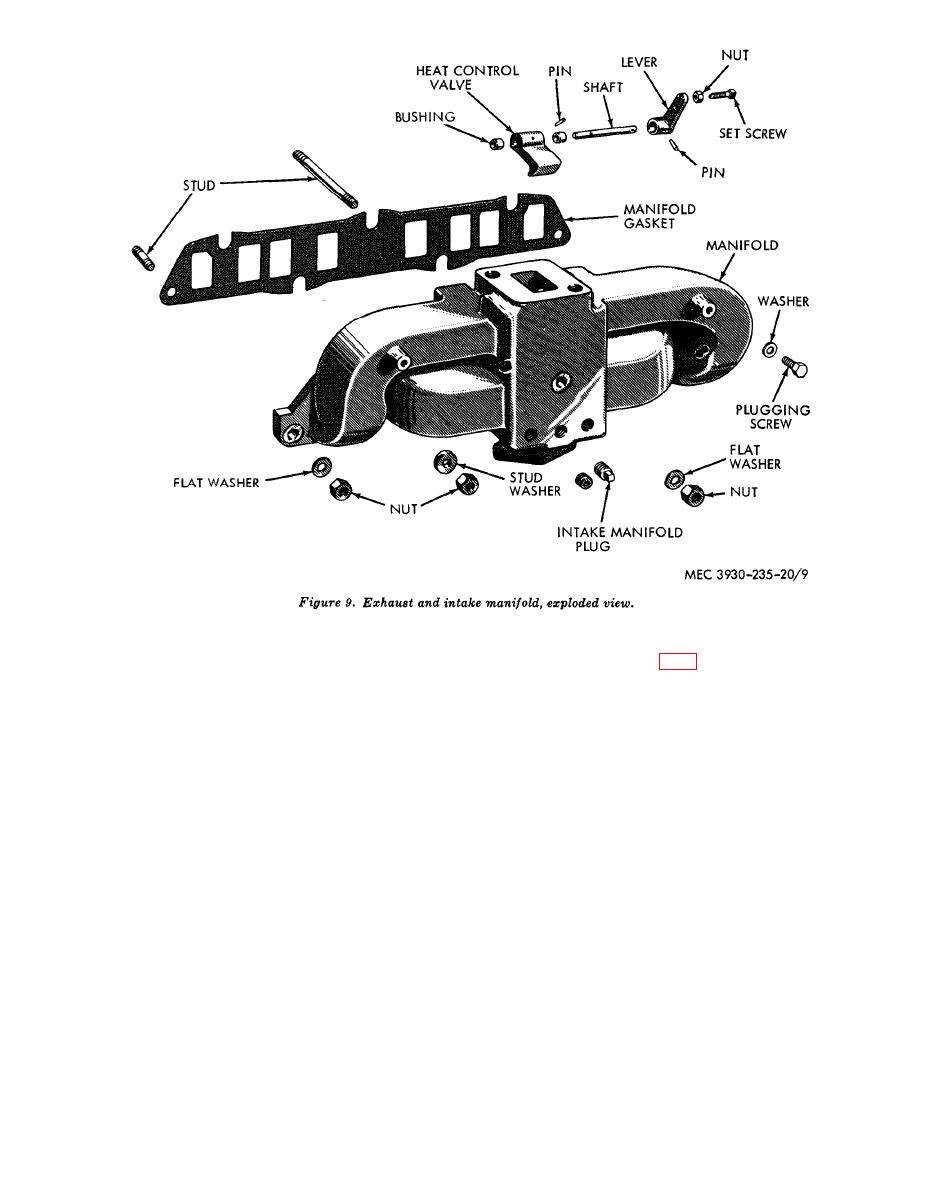 (6) Loosen clamp that attaches exhaust
engine intake and exhaust manifold is equipped
inlet pipe to muffler.
with a heat control valve (fig. 9) for the pur-
pose of preheating the engine fuel mixture.
(7) Loosen manifold elbow clamp and re-
The heat control valve is set at the factory in
move inlet pipe from muffler.
a fully closed position. Deviations from this
(8) Remove two brass nuts that attach
setting are not necessary unless cold weather
manifold elbow to manifold then work
conditions are encountered. Three position
elbow from manifold and remove el-
settings are provided. The fully closed position
bow.
allows exhaust gases to pass directly into the
(9) Remove 7 nuts, 3 flat washers, and 4
fully open position allows all burned exhaust
stud washers that attach manifold to
gases to circulate through the intake manifold,
cylinder block.
preheating the engine fuel mixture to a maxi-
(10) Pull manifold far enough from cyl-
mum. The intermediate position allows a por-
inder block to remove stud from center
tion of exhaust gases to circulate through the
of manifold. Remove stud.
intake manifold, while the remaining portion
(11) Remove manifold and gasket.
is directed out through the exhaust pipe and
b. Adjustment of Heat Control Valve. The
muffler.
AGO 6217A
|
|
Privacy Statement - Press Release - Copyright Information. - Contact Us |
