 |
|||
|
|
|||
|
Page Title:
Figure 6. Crankshaft and camshaft timing gears, showing correct alinement of timing marks. |
|
||
| ||||||||||
|
|
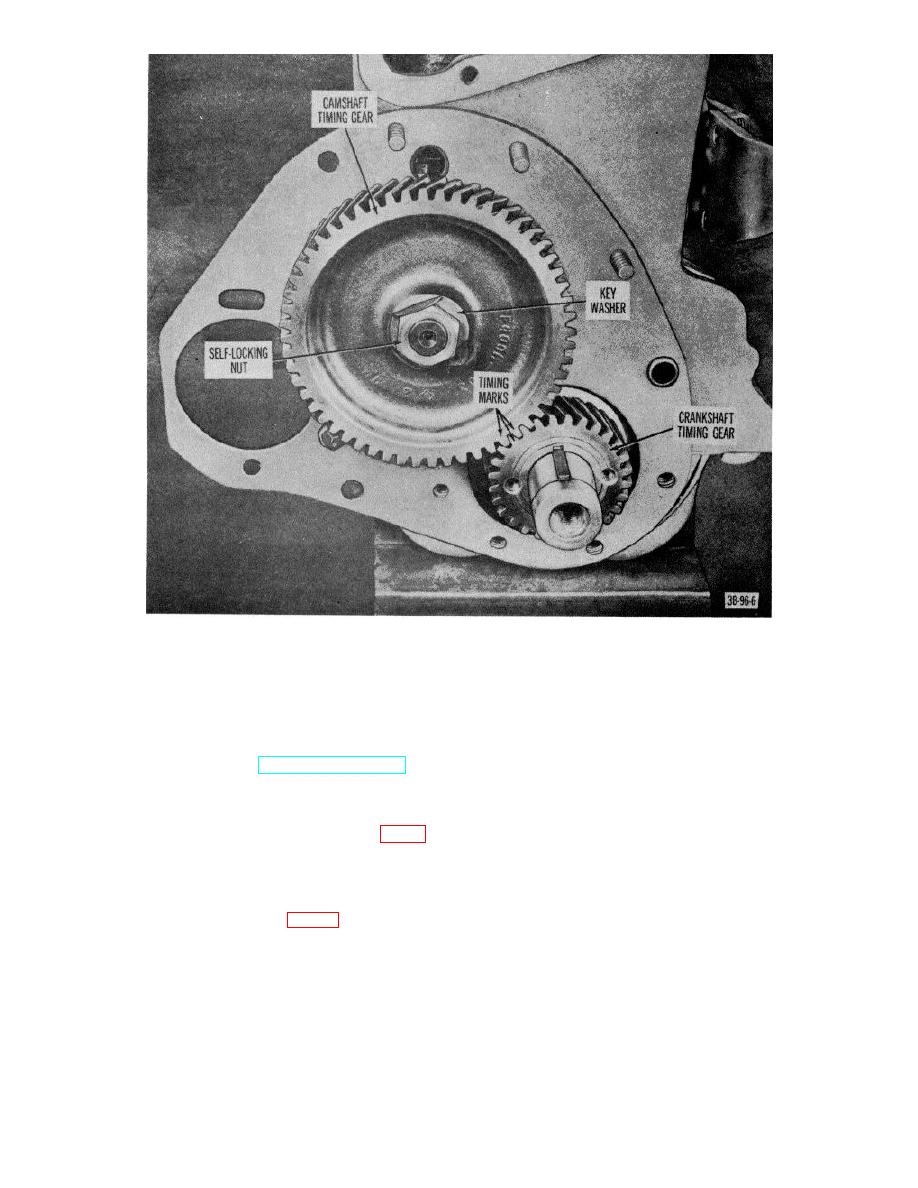 Figure 6. Crankshaft and camshaft timing gears, showing correct alinement of timing marks.
(8)
Tag each valve so it may be installed
22. Valves
in opening from which it was
removed.
a. Removal
b. Cleaning and Inspection.
(1) Remove cylinder head (TM 10-3930-
(1) Clean valves with SD. Use a wire
222-20).
wheel to remove carbon from valve
face, seat face, and from under head
and gaskets (TM 10-3930-222-20).
of valve.
(3) Remove valve cover-to-cylinder block
(2) After valves are thoroughly cleaned,
studs, sleeve nuts, and valve
inspect them for evidence of burns,
chamber cover and gasket.
correct margin, pit, grooves, crack
(4) Using valve spring compressor (fig. 8),
stem wear, lock or groove wear, and
and with valve in closed position,
warping.
compress spring and remove the
(3) If it is necessary to grind exhaust valve
valve spring locks.
faces, set chuck or refacing machine
(5) Remove spring compressor.
for 45 seat angle. For intake valve
(6) Remove valve (1, fig. 9), valve spring
set chuck for 30seat angle.
(7), valve spring seat (8), and cap (9).
(7) Repeat procedure in (4) through (6)
above for the other valves.
AGO 7010A
12
|
|
Privacy Statement - Press Release - Copyright Information. - Contact Us |
