 |
|||
|
|
|||
|
Page Title:
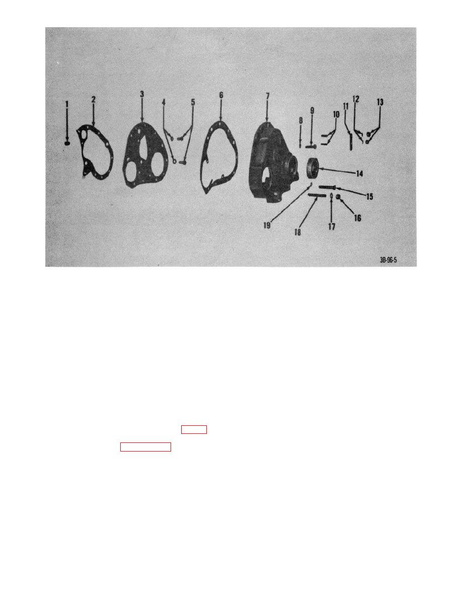
Figure 5. Timing gear over. exploded view. |
|
||
| ||||||||||
|
|
 1
Dowel, ring, front end plate
11 Plate, marker
2
Gasket, front end plate
12 Lockwashers
3
Plate, front end
13 Nuts
4
14 Seal, plain, incased, cover
6
Capscrews
15 Capscrew
6
Gasket, cover
16 Nut
7
Cover, timing gear
17 lockwasher
8
lockwasher
18 Stud
9
Capscrew
19 Washer, flat
10
Stud, plain
Figure 5. Timing gear over. exploded view.
(2) Use an outside micrometer to measure
(1)
If sleeve bushings were removed for
the diameter of each camshaft
replacement, press bearings into
journal. If journal wear exceeds 0.002
position with a suitable bearing press.
inch, install new camshaft.
(2) Oil the camshaft journals and sleeve
(3) Use an inside micrometer or telescope
bearings and ease camshaft into
gage, and measure camshaft sleeve
position in cylinder block. The rear
bearings (8, 9, 10, and 11, fig. 7). If
end of the camshaft must be
clearance is not to specifications
supported and guided to prevent
listed in paragraph 7, install new
damage.
sleeve bearings at all journals. Be
(3) Untie the valve lifters and return them
certain that oil passages are alined
back into position.
and open.
(4) Reverse procedures (1) through (6) in a
(4) Inspect thrust plate and cams for wear;
above.
inspect journals and cams for scoring.
c. Installation.
AGO 7010A
11
|
|
Privacy Statement - Press Release - Copyright Information. - Contact Us |
