 |
|||
|
|
|||
|
Page Title:
Figure 3 . Removing engine assembly, torque converter, and transmission. |
|
||
| ||||||||||
|
|
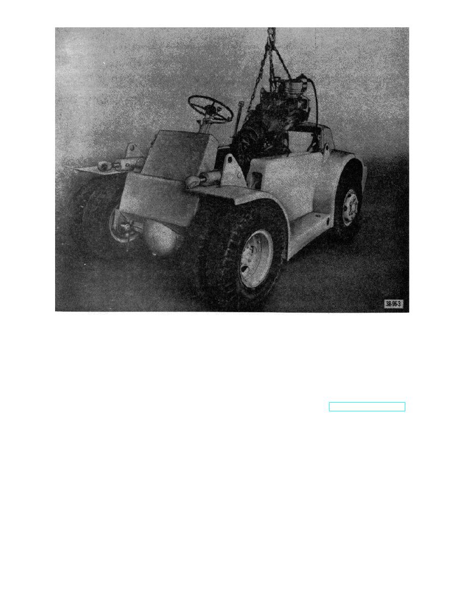 Figure 3 . Removing engine assembly, torque converter, and transmission.
(1) Clean parts with SD.
(6) Replace any of these parts that are
(2) Inspect parts for serviceability and, if found
unserviceable.
unserviceable, replace pump.
d. Installation. Reverse procedure in b above.
c. Assembly and Installation. Reverse procedure in
e. Adjustment.
a above.
(1) Add washers to increase pressure.
(2) Remove washers to decrease pressure.
17. Fan Drive Pulley a. Removal.
(1) Remove radiator (par. 35).
16. Oil Pump Assembly
(2) Remove main pump drive shaft (par. 59a).
a. Removal and Disassembly.
(3) Remove fan belt (TM 10-3930-222-20).
(1) Remove oil pan (par. 14).
(4) Remove screw and washer that secure pulley to
(2) Remove nut and lockwasher from pump-to-
crankshaft and remove pulley.
bearing cap stud and remove oil pump from
b. Installation. Reverse procedure in a above.
cylinder block.
(3) Remove the wire securing screen to pump, and
remove screen.
b. Cleaning and Inspection.
AGO 7010A
8
|
|
Privacy Statement - Press Release - Copyright Information. - Contact Us |
