 |
|||
|
|
|||
|
Page Title:
Figure 2. Transmission control valve and linkage. |
|
||
| ||||||||||
|
|
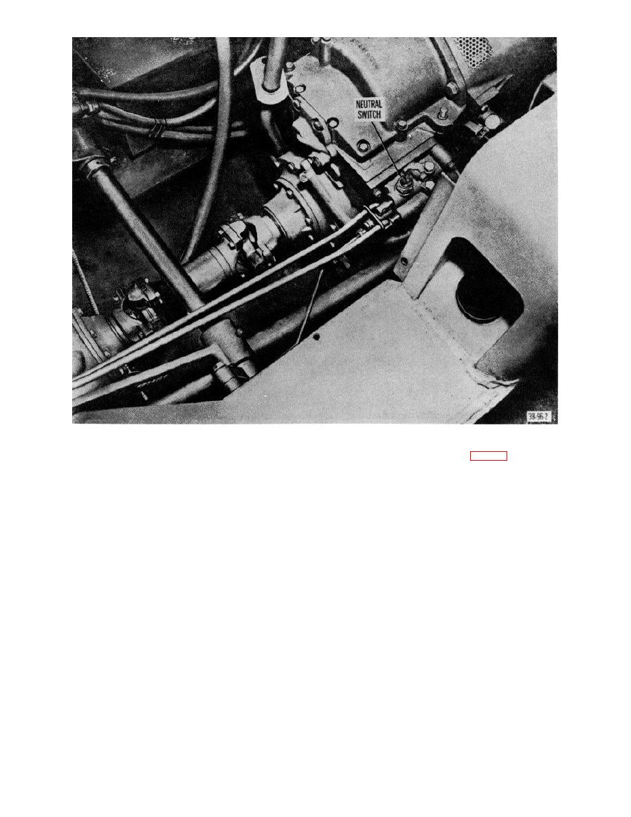 Figure 2. Transmission control valve and linkage.
b. Removal
(1) Clean oil pan with SD (solvent, drycleaning).
(2) Beat out dents using a hammer and a block.
(1) Remove the plug (32, fig. 4).
(3) Braze or weld any minor cracks.
(2) Remove adjusting washers if there are any.
c. installation.
Reverse procedure in a above,
(3) Remove the spring.
using new gasket.
(4) Remove the valve (34).
c. Cleaning, Inspection, and Repair.
(1) Clean all parts with SD.
15. Oil Pressure Relief Valve
(2) Check to see that plug threads are in good
a. General. The oil pressure relief valve is located
condition.
on the right side of the engine and opens at 45 to 50
(3) Check to see that the adjusting washers are
pounds of pressure. If the oil pressure gage is not
present.
defective and the pressure shown is less than 45 pounds
(4) Check the spring for breakage and fatigue.
at operating speed, the oil pressure relief valve may not
(5) Examine the valve for wear or mechanical
be seated properly and must be removed and inspected.
defects.
7
|
|
Privacy Statement - Press Release - Copyright Information. - Contact Us |
