 |
|||
|
|
|||
|
Page Title:
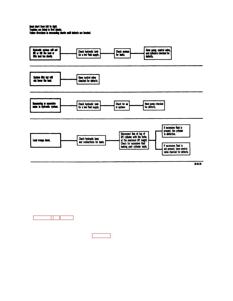
Figure 11. Hydraulic troubleshooting chart. |
|
||
| ||||||||||
|
|
 TM 10-3930-222-20
Figure 11. Hydraulic troubleshooting chart.
Section IV. ENGINE (GROUP 01)
a. Removal.
17. General
The engine is a six-cylinder, four-stroke cycle, L-head,
(1)
Drain the cooling system by opening a
gasoline type. It is provided with a full-pressure, force-
drain valve at the bottom of the radiator
feed lubricating system.
Engine temperature is
and another just under the generator on
controlled by a bypass thermostat, an impeller-type
the engine block.
water pump, and a cored cylinder head. The engine is
(2)
Loosen the hose clamps on the upper
illustrated in figures 12, 13, and 14.
radiator hose (1) and remove the hose
from the water outlet elbow (2).
18. Cylinder Hood
(3)
Disconnect the water recirculating tube (9)
The cylinder head contains the combustion chambers
between the elbow and the water body.
and cored passages for water flow. Refer to figure 15
(4)
Disconnect and tag all spark plug wires.
and remove the cylinder head as follows.
50
|
|
Privacy Statement - Press Release - Copyright Information. - Contact Us |
