 |
|||
|
|
|||
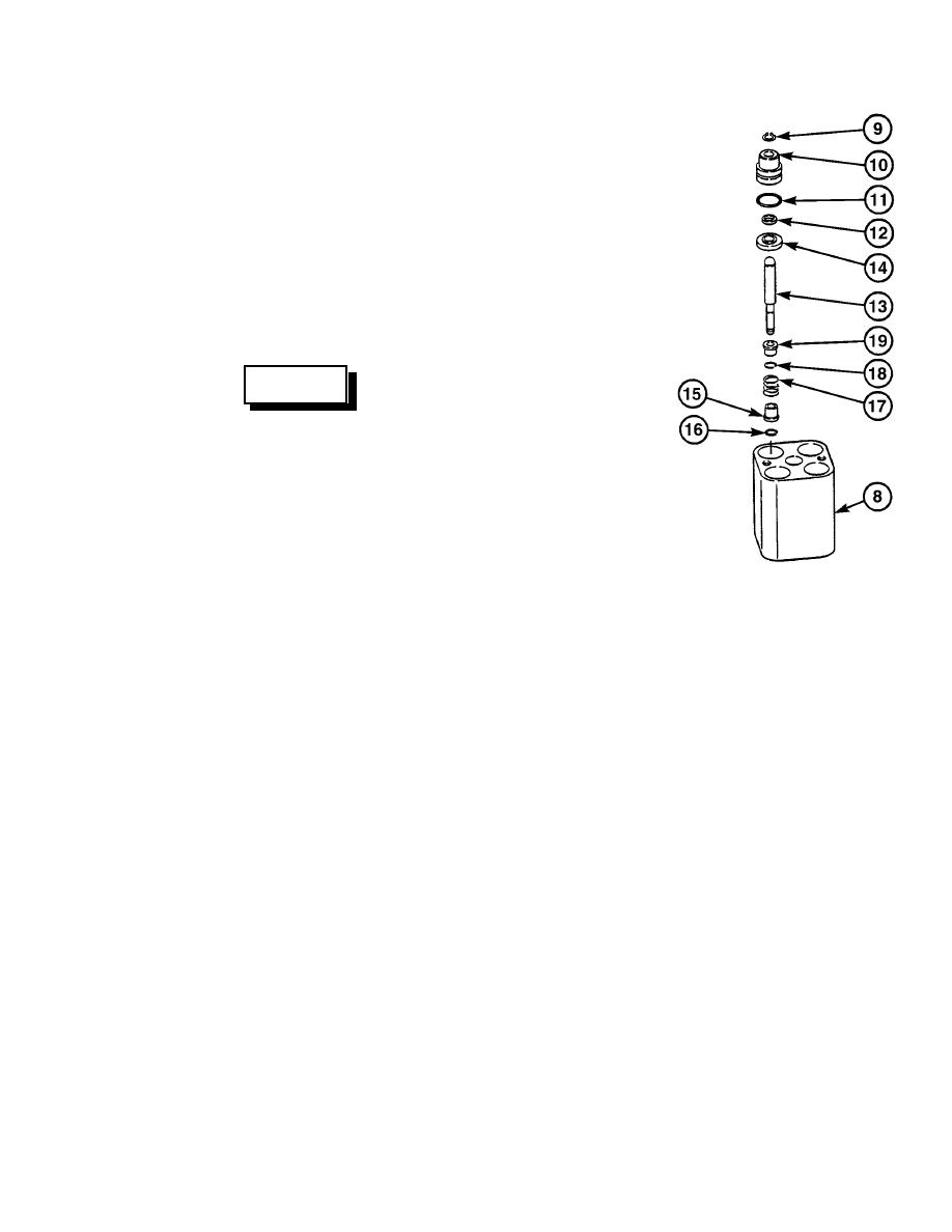
|
Page Title:
HYDRAULIC JOYSTICK CONTROL VALVE REPAIR - continued |
|
||
| ||||||||||
|
|
 TM 10-3930-673-34
NOTE
Hydraulic joystick control valve
contains four plunger capsule
assemblies and four metering
capsule assemblies. All four plunger
capsule assemblies and metering
capsule assemblies are removed the
same way.
(5)
Remove plunger capsule parts (9
through 19) from housing (8).
WARNING
Use care when removing snap and
retaining rings. Snap and retaining
rings are under spring tension and
can act as projectiles when released
and could cause severe eye injury.
(a)
Remove retaining ring (9), cap (10),
preformed packing (11), and
seal (12) from plunger (13) and
TR01769
housing (8). Discard preformed
packing and seal.
(b)
Remove retainer (14) from plunger (13) and housing (8).
(c)
Push up on spring seat (15) and remove retaining ring (16) and spring seat from plunger (13)
housing (8).
(d)
Remove spring (17), retaining ring (18), and spring seat (19) from plunger (13) and
housing (8).
16-127
|
|
Privacy Statement - Press Release - Copyright Information. - Contact Us |