 |
|||
|
|
|||
|
Page Title:
TANDEM GEAR PUMP REPAIR - continued |
|
||
| ||||||||||
|
|
 TM 10-3930-673-34
(d)
Install seal (28) in thrust plate (27) with flat side of seal facing away from thrust plate.
(e)
Install thrust plate (27) through gear housing (19) into end cover (30). Seal (28) should face
away from end cover (30). The relief groove in thrust plate should face pump outlet side.
(f)
Install driven gear (24) through gear housing (19) into end cover (30).
(g)
Apply grease on fabricated drive gear installation tool. Place shaft of greased drive gear (21)
inside tool. Slide both through end cover (30) with a twisting motion. The integral gears
should rest against thrust plate (27). Remove drive gear installation tool. Apply oil on drive
gear and driven gear (24).
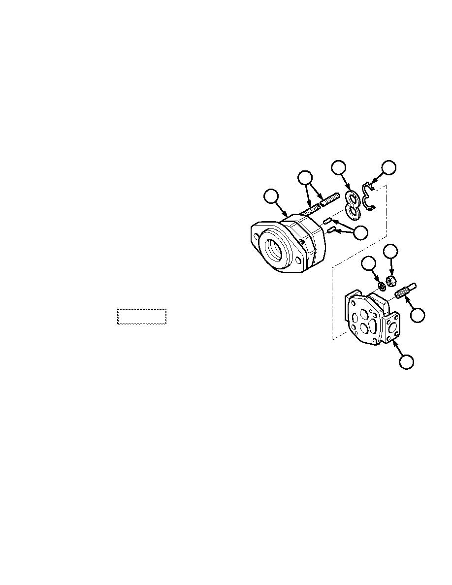
(3)
Install bearing carrier (3) and
22
23
parts (16, 17 and 20 through 23) on
18
gear housing (19).
19
(a)
If removed, install dowel pins (25) in
bearing carrier (3) and gear
housing (19).
25
(b)
Install seal (23) in thrust plate (22)
with flat side of seal facing away
from thrust plate.
16
17
(c)
Install thrust plate (22) over
gears (21 and 24) and into gear
housing (19) bore.
CAUTION
20
If parts are difficult to fit during
assembly, tap with a soft hammer.
Use care to prevent part damage.
3
(d)
Ensure that dowel pins (25) are in
TR01296
place. Install bearing carrier (3)
onto gear housing (19). Align dowel
holes over dowel pins. Use a soft
hammer to tap bearing carrier and gear housing together.
(e)
Install four washers (17) and nuts (16) on studs (18).
(f)
Install connecting shaft (20) in spline of drive gear (21).
16-13
|
|
Privacy Statement - Press Release - Copyright Information. - Contact Us |