 |
|||
|
|
|||
|
Page Title:
TRANSMISSION ASSEMBLY REPLACEMENT/REPAIR - continued |
|
||
| ||||||||||
|
|
 TM 10-3930-673-34
WARNING
Use care when installing snap and
retaining rings. Snap and retaining
rings are under spring tension and
can act as projectiles when released
and could cause severe eye injury.
(h)
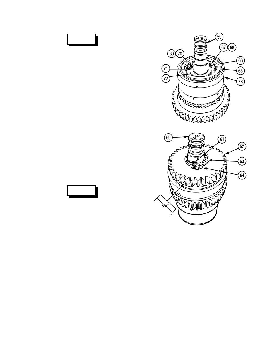
Install retainer (66) and snap
ring (65) on shaft assembly (59).
(i)
Install appropriate pair of alignment
bars between weld gear (70) and
piston (73), as required, to hold weld
gear off piston. Use either narrow or
wide side of bars to ensure that weld
gear is held off piston 5/8 in. (15.9
TR00294
mm) and at the same time engages
all clutch plates (67).
(j)
Install weld gear (70) on shaft
assembly (59). Turn weld gear so it
meshes with clutch plates (67) and
separator plates (68). Push weld
gear until it bottoms out. Weld gear
splines must be in full position with
internal teeth of all clutch plates.
WARNING
Use care when installing snap and
retaining rings. Snap and retaining
rings are under spring tension and
can act as projectiles when released
and could cause severe eye injury.
TR00223
(k)
Using an assistant to spread snap
ring (64), use a bearing driver to
press bearing (63) onto shaft assembly (59) and into weld gear (62). Remove alignment bars to
seat bearing and weld gear as an assembly.
(l)
Install snap ring (61). Ensure that snap ring is fully in groove of shaft assembly (59).
7-27
|
|
Privacy Statement - Press Release - Copyright Information. - Contact Us |