 |
|||
|
|
|||
|
Page Title:
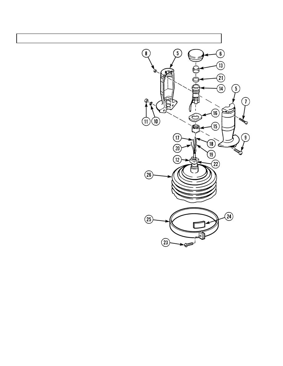
Handle Pushbutton Switch Installation. |
|
||
| ||||||||||
|
|
 TM 10-3930-673-34
6-7. ELECTRIC JOYSTICK ASSEMBLY REPAIR/TEST/ADJUSTMENT (CONT)
d. Handle Pushbutton Switch Installation.
(1)
Assemble parts (12, 15, 16, and 21
through 26) and solder four wires (17
through 20) to pushbutton
switch (14).
(a)
If removed, install boot (26),
clamp (25), band (24), and
screw (23).
(b)
If removed, install shaft
coupling (12) and set screw (22).
(c)
Install cover (21) on pushbutton
switch (14).
(d)
Install flange (16) and nut (15) on
pushbutton switch (14).
(e)
Solder four wires (17 through 20) to
pushbutton switch (14).
(2)
Install parts (6 through 11) and
parts (13 through 16) in handle
sections (5).
NOTE
Align handle section on shaft
coupling so that coupling set screw
is facing center of handle section.
(a)
Place one handle section (5) on shaft
coupling (12).
TR01119
NOTE
Place switch flange in lowest slot
with flat surface of flange facing
center of handle section.
(b)
Install pushbutton switch (14), flange (16), and nut (15) as an assembly in handle section (5).
(c)
Install actuating button (13) with larger diameter of button extending through top of handle
section (5).
(d)
Place other handle section (5) on shaft coupling (12).
(e)
Install two screws (9), bowed washers (10), and nuts (11) at bottom of handle sections (5).
6-30
|
|
Privacy Statement - Press Release - Copyright Information. - Contact Us |
