 |
|||
|
|
|||
|
|
|||
| ||||||||||
|
|
 TM 10-3930-673-34
NOTE
Cylinder head has integral valve
guides. Service valve guides can be
installed to meet tolerance
specifications after cylinder head is
machined.
(4)
Inspect valve guide bores.
Inspect valve guide bores for scuffing or
scoring. If guide bores are scuffed or
scored, service valve guides must be
TR00611
installed. See Step e. Repair.
(5)
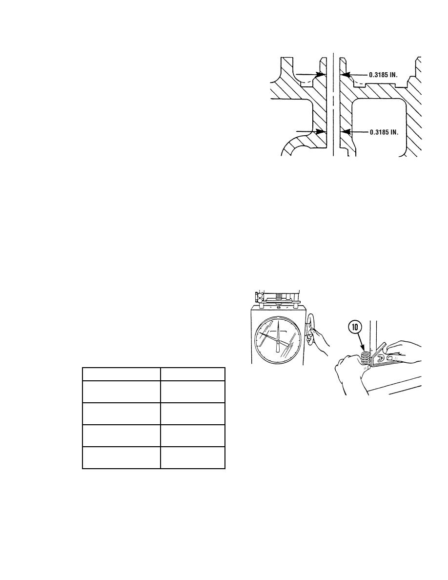
Measure valve guide bore. Maximum
allowable diameter is 0.3185 in. (8.09 mm).
If guide bores are worn, service valve guides must be installed. See Step e. Repair.
(6)
Inspect valve seats.
(a)
Inspect valve seats for scoring, scratches, or burned condition.
(b)
If a valve seat is scored, scratched, or burned it must be ground or replaced. See
Step e. Repair.
(7)
Inspect valve springs (10).
Visually inspect valve springs for nicks,
deep scratches, rust deposits, notches at
end of spring, and for wear between coils.
(8)
Using valve spring tester, check
spring force.
Description
Specification
Test force
65.0 - 72.2 lb
(29.48 - 32.75 kg)
TR00612
Length under test
1.94 in.
force
(49.28 mm)
Free length after test
2.19 in.
(55.63 mm)
Spring must not be
0.039 in.
bent more than
(0.99 mm)
3-43
|
|
Privacy Statement - Press Release - Copyright Information. - Contact Us |