 |
|||
|
|
|||
|
|
|||
| ||||||||||
|
|
 TM 10-3930-673-20-2
18-13. FRAME TILT CYLINDER REPLACEMENT (CONT)
(4)
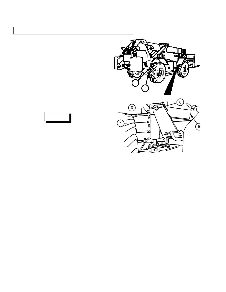
Install base pivot pin (3) in vehicle frame (5)
and frame tilt cylinder (4).
(a)
Start engine (TM 10-3930-673-10).
(b)
Extend frame tilt cylinder (4) to align rod
end hole and upper bracket hole.
(c)
Stop engine (TM 10-3930-673-10).
1
(d)
Apply anti-seize compound to base pivot
2
pin (3).
TR00585
(e)
Install base pivot pin (3) in vehicle frame
(5) and frame tilt cylinder (4).
WARNING
Use care when installing snap and
retaining rings. Snap and retaining rings
are under spring tension and can act as
projectiles when released and could cause
severe eye injury.
(f)
Install retaining ring (6) on base pivot pin
TR00508
(3).
(5)
Remove wood blocks from between both rear frame tilt stop pads (1) and rear axle (2).
NOTE
It is possible that hydraulic pumps have air in pump cavities. Air must be purged from cavity before
pump will operate.
(6)
Purge frame tilt hydraulic circuit.
(a)
Start engine (TM 10-3930-673-10).
(b)
Purge air from frame tilt cylinder hydraulic circuit by operating frame tilt function five times.
(c)
Stop engine and relieve hydraulic pressure by operating frame tilt controls
(TM 10-3930-673-10).
END OF TASK
18-80
|
|
Privacy Statement - Press Release - Copyright Information. - Contact Us |