 |
|||
|
|
|||
|
|
|||
| ||||||||||
|
|
 TM 10-3930-673-20-2
18-8. RELIEF VALVE, FRAME TILT/BRAKES TEST/REPLACEMENT (CONT)
c. Adjustment.
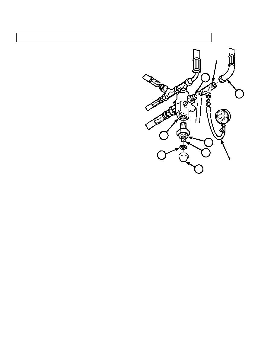
TEST TEE
(1)
Remove relief valve inlet hose (4) and install
test tee in relief valve (14).
(a)
Remove relief valve inlet hose (4) from
9
relief valve inlet port (9).
(b)
Install test tee in relief valve inlet port (9).
4
(c)
Install inlet hose (4) on test tee.
(2)
Connect 0 - 5000 psi (0 - 34475 kPa) pressure
gauge on test tee.
(3)
Start engine (TM 10-3930-673-10).
14
24
NOTE
23
Engine may be operated at idle or full
22
throttle when performing pressure
tests.
PRESSURE
G
21
AUGE
Pressure must read between 2,600 - 2,700 psi
TR00799
(17927 - 18616 kPa).
(4)
Read relief valve pressure on gauge. If relief
valve pressure is not within specifications, adjust as follows:
(a)
Remove acorn nut (21) and washer (22) covering slotted head adjusting screw (23).
(b)
Hold adjusting screw and loosen/back off jam nut (24).
(c)
To increase relief pressure, turn adjusting screw (23) clockwise (in). To decrease pressure, turn adjusting
screw counterclockwise (out).
(d)
When desired relief pressure is obtained, hold adjusting screw in position and tighten jam nut (24). Install
washer (22) and acorn nut (21).
(5)
Shut off engine (TM 10-3930-673-10).
18-54
|
|
Privacy Statement - Press Release - Copyright Information. - Contact Us |
