 |
|||
|
|
|||
|
|
|||
| ||||||||||
|
|
 TM 10-3930-673-20-2
NOTE
32
20
Apply coating of clean hydraulic oil to all
seals as they are installed.
30
31
19
(2)
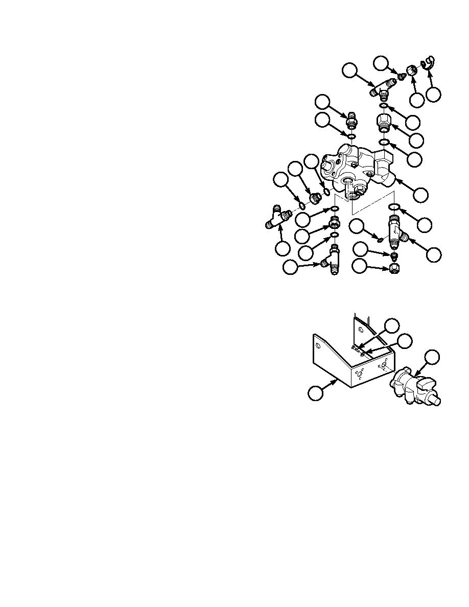
Install preformed packings (34 through 41),
fittings (25 through 33), and (6, 17 through
39
40
20) on service brake control valve (23).
33
(a)
Install adapter (33), tee (20) and
preformed packings (40 and 41) on
41
service brake control valve (23).
38
29
(b)
Install nipple (32), nut (31), and cap (30)
37
on tee (20).
23
(c)
Install adapter (19) and preformed
packing (39).
36
34
25
(d)
Install adapter (29), tee (18), and
28
preformed packings (37 and 38).
18
27
35
6
(e)
Install adapter (28), tee (17), and
26
17
preformed packings (35 and 36).
TR00596
(f)
Install reducer (27), nut (26), adapter
(25), tee (6) and preformed packing (34).
(3)
Install service brake control valve (23) on
bracket (24) with mounting hardware (parts
21
21 and 22).
22
(a)
Position and support service brake control
23
valve (23) on bracket (24).
(b)
Apply sealing compound to threads of
three screws (21).
24
(c)
Install valve (23) on bracket (24) with
TR00595
three lockwashers (22) and screws
(21).
12-21
|
|
Privacy Statement - Press Release - Copyright Information. - Contact Us |