 |
|||
|
|
|||
|
|
|||
| ||||||||||
|
|
 TM 10-3930-673-20-2
(3)
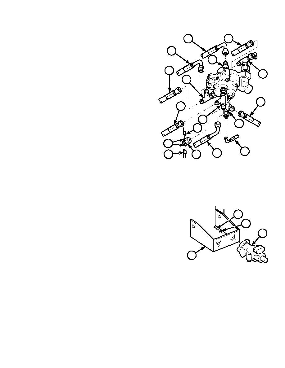
Remove sensor (5) from elbow (6).
16
15
(a)
Tag, mark, and disconnect two electric
14
wires (7) from connectors (8).
19
(b)
Remove sensor (5) from tee (6).
13
20
NOTE
18
Hose in Step (4)(a) below is connected
directly to accumulator. Hose should be
plugged with #12 plug immediately after
9
disconnecting from valve.
12
(4)
Tag, mark, and remove eight hydraulic hoses
(9 through 16) from fittings (6, 17 through
17
6
20).
7
(a)
Tag, mark, and remove hoses (9 and 10)
from tee (6).
8
10
(b)
Tag, mark, and remove hose (11) and hose
11
7
5
(12) from tee (17).
TR00594
(c)
Tag, mark, and remove hose (13) and
hose (14) from tee (18).
(d)
Tag, mark, and remove hose (15) from adapter (19).
(e)
Tag, mark, and remove hose (16) from tee (20).
(5)
Remove mounting hardware (parts 21 and
22) and service brake control valve (23) from
21
bracket (24).
22
NOTE
23
Support service brake control valve so
valve does not drop during hardware
removal.
24
Remove three screws (21), lockwashers (22),
TR00595
and service brake control valve (23) from
bracket (24). Discard lockwashers.
12-19
|
|
Privacy Statement - Press Release - Copyright Information. - Contact Us |