 |
|||
|
|
|||
|
|
|||
| ||||||||||
|
|
 TM 10-3930-673-20-2
8-53. HYDRAULIC BYPASS SWITCH TEST/REPLACEMENT (CONT)
NOTE
If voltage requirements are not met in
Steps (2)(a) through (2)(f) above, perform
continuity tests in Step (3) below.
(3)
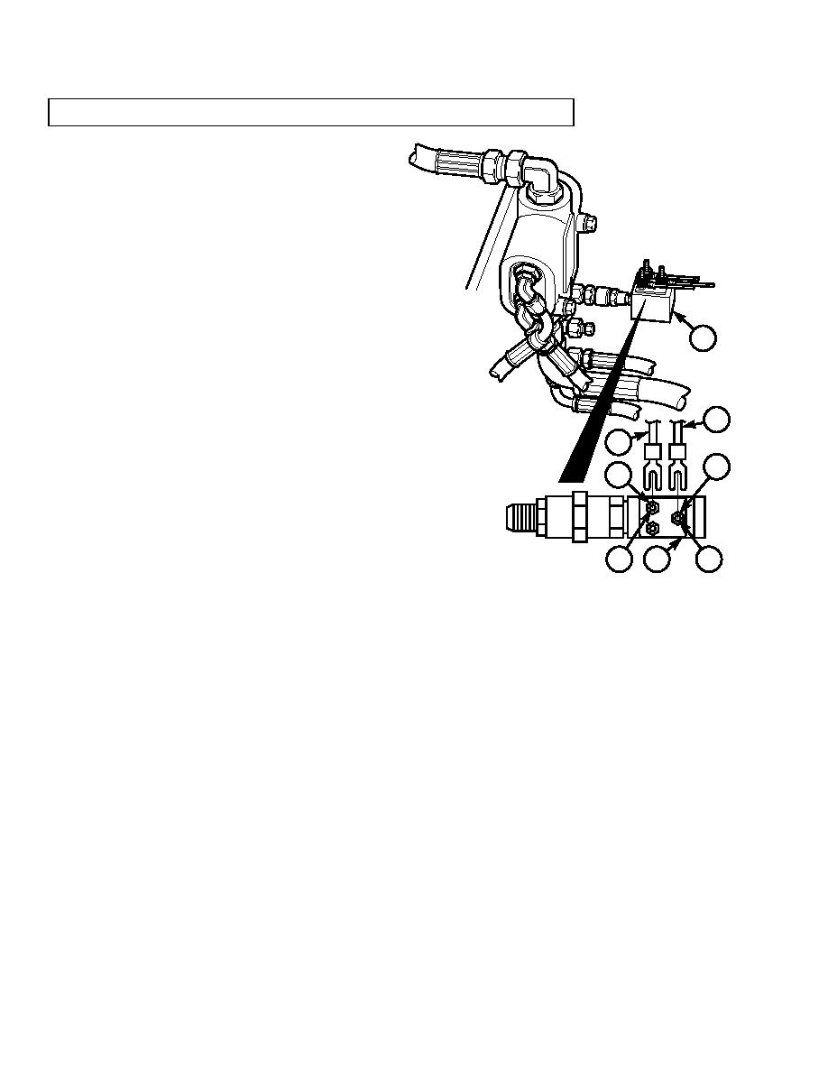
Perform continuity tests on hydraulic bypass
switch (1).
(a)
Loosen nut (2). Tag, mark, and remove
electrical wire 91 (3) from terminal NC (4) of
hydraulic bypass switch (1).
1
(b)
Loosen nut (5). Tag, mark, and remove
electrical wire 10 (6) from terminal C (7) of
hydraulic bypass switch (1).
6
(c)
Connect positive lead of multimeter to terminal
NC (4) of hydraulic bypass switch (1).
3
91
10
5
(d)
Connect negative lead of multimeter to terminal
2
C (7) of hydraulic bypass switch (1).
NC
C
(e)
Multimeter should indicate continuity.
NO
(f)
Start engine (TM 10-3930-673-10).
4
1
7
(g)
Multimeter should indicate no continuity.
TR00825
(h)
Stop engine (TM 10-3930-673-10).
NOTE
If continuity requirements are not met in Steps (3)(a) through (3)(h), hydraulic bypass switch is
defective and must be replaced (refer to b. Removal and c. Installation below).
(i)
Disconnect leads of multimeter from terminal NC (4) and terminal C (7) of hydraulic bypass switch (1).
(j)
Connect electrical wire 10 (6) to terminal C (7) of hydraulic bypass switch (1) and tighten nut (5).
(k)
Connect electrical wire 91 (3) to terminal NC (4) of hydraulic bypass switch (1) and tighten nut (2).
8-174
|
|
Privacy Statement - Press Release - Copyright Information. - Contact Us |
