 |
|||
|
|
|||
|
|
|||
| ||||||||||
|
|
 TM 10-3930-673-20-2
(3)
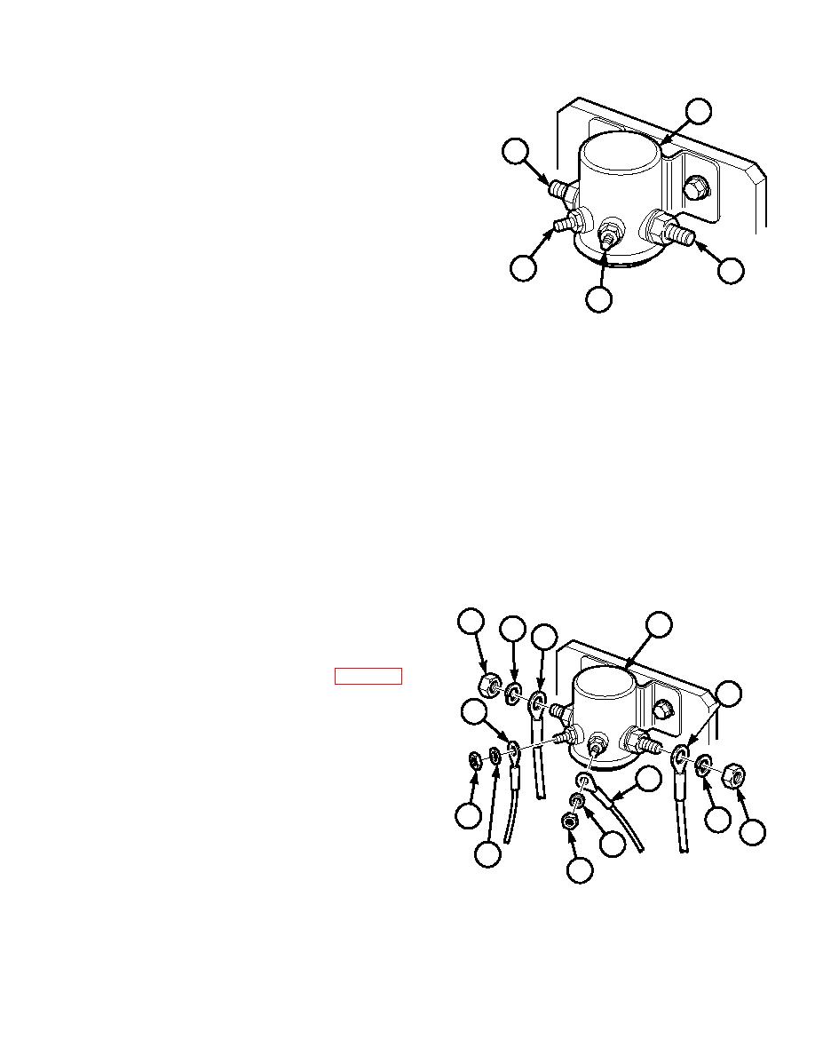
Test starter relay (5) for proper solenoid
5
operation.
(a)
Apply 24 VDC to relay terminals (8 and
10
9).
(b)
Listen for "click" when voltage is
applied. If no "click" is heard, replace
relay (perform Removal and
Installation sections of this paragraph).
8
11
(c)
If "click" is heard, go on to Step (4)
below.
9
(4)
Test starter relay (5) for continuity.
TR00331
(a)
Apply 24 VDC to relay terminals (8 and
9).
(b)
Connect multimeter across relay terminals (10 and 11).
(c)
Multimeter should show continuity across terminals (10 and 11).
(d)
Remove 24 VDC from terminals (8 and 9).
(e)
Multimeter should show no continuity across terminals (10 and 11).
(f)
If continuity requirements are not met in Steps (4)(c) and (4)(e), above, replace relay (perform Removal
and Installation sections of this paragraph).
(g)
If continuity requirements are met, perform Steps (5) and (6) below.
(5)
Install four electrical wires (1 through 4) on
6
5
7
starter relay (5) with lockwashers (7) and
4
nuts (6).
(6)
Connect negative battery cable (Para 8-44).
1
3
b. Removal.
NOTE
If relay has been tested, begin Removal at Step
2
(3) below.
6
7
(1)
Tag and mark four electrical wires (1
6
through 4) on starter relay (5).
7
7
(2)
Remove four nuts (6), lockwashers (7), and
6
electrical wires (1 through 4) from starter
TR00330
relay (5). Discard lockwashers.
8-63
|
|
Privacy Statement - Press Release - Copyright Information. - Contact Us |
