 |
|||
|
|
|||
|
|
|||
| ||||||||||
|
|
 TM 10-3930-673-20-2
6
1
2
2
1
6
3
7
5
4
TR00321
c. Installation.
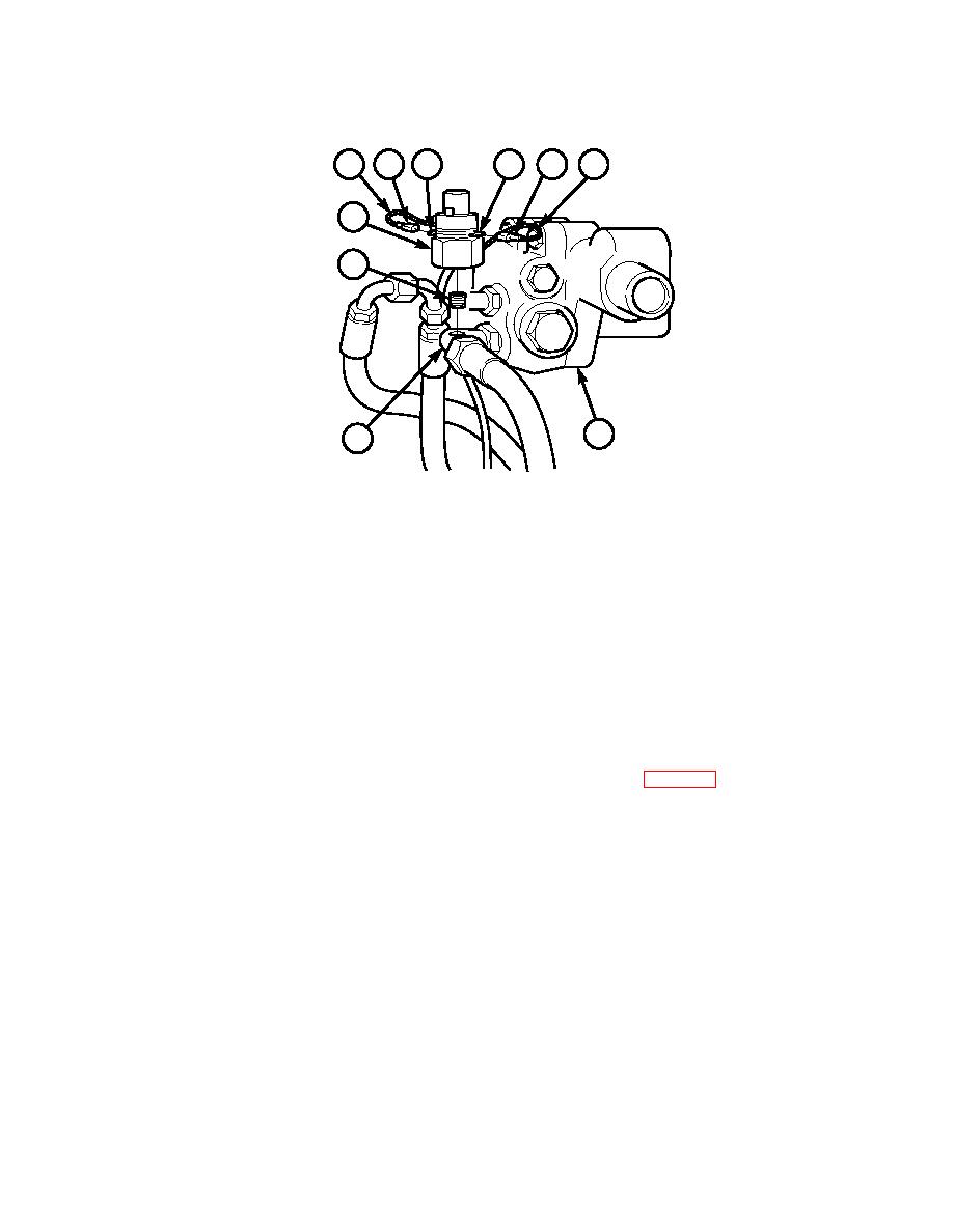
Install brake hydraulic pressure switch (3) on elbow (4) of brake control valve (5).
(a)
Apply sealing compound to threads of brake hydraulic pressure switch (3) and nipple (7).
(b)
Install nipple (7) in elbow (4).
(c)
Install brake hydraulic brake pressure switch (3) on nipple (7).
(d)
Connect two connectors (1) of vehicle wiring harness (6) to connectors (2) on brake hydraulic pressure
switch (3). Apply anti-fungus varnish to connectors (1 and 2).
NOTE
Follow-on Maintenance: Connect negative battery cable (Para 8-44).
END OF TASK
8-45
|
|
Privacy Statement - Press Release - Copyright Information. - Contact Us |