 |
|||
|
|
|||
|
|
|||
| ||||||||||
|
|
 TM 10-3930-673-20-2
(2)
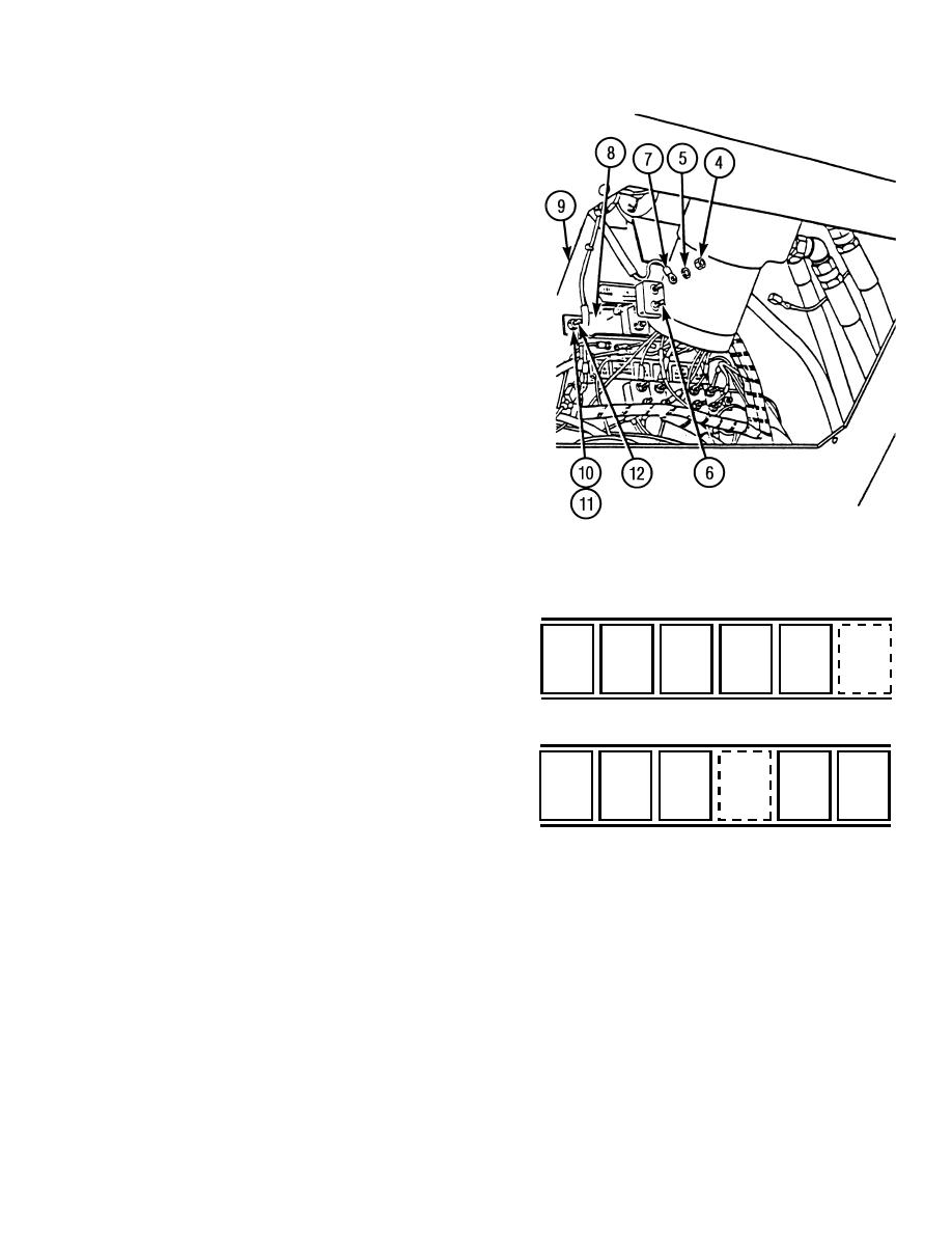
Remove two nuts (4) and lockwashers (5)
from circuit breaker (6). Tag, mark, and
remove electrical wires (7). Discard
lockwashers.
(3)
Remove circuit breaker (6) from bracket (8).
(4)
If damaged, remove bracket (8) from cab (9).
(a)
Tag, mark and remove all circuit breakers
(6) from bracket (8) to be removed by
pulling breaker straight out of bracket.
(b)
Remove two nuts (10), lockwashers (11),
and bracket (8) from cab (9). Discard
lockwashers.
(c)
From outside of cab (9) remove two
screws (12).
b. Installation.
NOTE
TR00909
Circuit breakers are positioned as shown in
figure at right.
Circuit
Breaker
Amps
OPEN
CB1
CB3
CB5
CB8
CB10
CB1
6
SPACE
CB2
6
GAUGES
WIPER
AUTO
HEATER
HORN
CB3
20
WASHER
LEVEL
FAN
TURN
SIGNALS
CB4
15
CB5
6
OPEN
CB4
CB6
CB7
CB2
CB9
SPACE
CB6
40
CB7
15
BACK UP
STEER
MAIN
FLOOD
B.O. LTS
ALARM
SELECT
POWER
LIGHTS
SERV LTS
PANEL LTS
CB8
15
TR00910
CB9
6
CB10
10
8-31
|
|
Privacy Statement - Press Release - Copyright Information. - Contact Us |
