 |
|||
|
|
|||
|
Page Title:
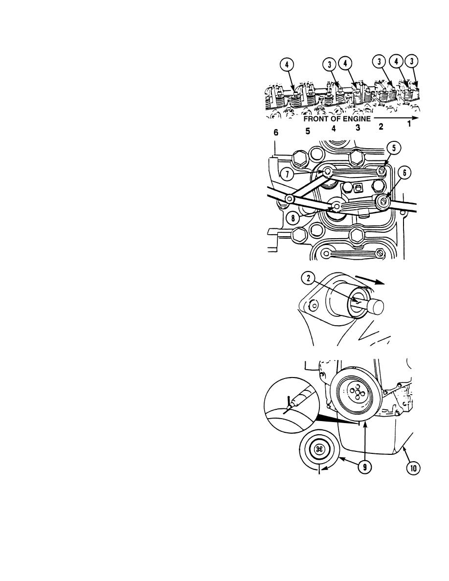
INTAKE AND EXHAUST VALVE ADJUSTMENT-CONT. |
|
||
| ||||||||||
|
|
 TM 10-3930-673-20-2
(2)
Adjust clearances of three intake valves (3) and
three exhaust valves (4) shown.
NOTE
Clearance is correct when a slight pull
is felt as feeler gage is slipped between
valve stem and rocker lever.
Intake valve clearance - 0.010 in.
(0.254 mm).
Exhaust valve clearance - 0.020 in.
(0.508 mm).
(a)
Loosen adjustment locknut (5). Adjust screw
(6) as required until clearance between valve
stem (7) and rocker lever (8) is properly
adjusted.
(b)
Tighten adjustment locknut (5) to
216 lb-in. (24.4 Nm). Then recheck valve
clearance.
(3)
Disengage engine timing pin (2).
(4)
Matchmark crankshaft pulley (9) and oil pan
(10).
TR00150
4-5
|
|
Privacy Statement - Press Release - Copyright Information. - Contact Us |
