 |
|||
|
|
|||
|
Page Title:
CAB BLOWER DOES NOT OPERATE - continued |
|
||
| ||||||||||
|
|
 TM 10-3930-673-20-1
VOLTAGE TEST
(1) Set multimeter to volts dc.
(2) Connect multimeter positive lead (+) to
fan switch where high (orange wire),
medium (light blue wire), low (yellow
wire) connects pins 1, 3, or 6.
(3) Connect multimeter negative lead () to
known good ground.
(4) Turn engine start switch to ON position,
BUT DO NOT START ENGINE
(TM 10-3930-673-10).
(5) Turn heater/air conditioner switch to
Heat (TM 10-3930-673-10)
(6) Cycle through all fan speeds, High,
Medium, Low (TM 10-3930-673-10).
ORANGE
W
(a) If voltage is present, go to Step 4
IRE
of this fault.
W
LT BLUE
(b) If voltage is not present, replace
IRE
YELLOW
W
fan switch (Para 17-9).
(7) Turn heater/air conditioner switch OFF
IRE
(TM 10-3930-673-10)
(8) Turn engine start switch to OFF
position (TM 10-3930-673-10).
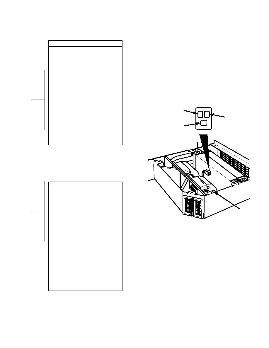
VOLTAGE TEST
(1) Remove seat (Para 16-12).
(2) Set multimeter to volts dc.
(3) Connect multimeter positive lead (+) to
fan Resistor Pack connector J1 where
high (orange wire), medium (light blue
RESIPTOR
S
wire), low (yellow wire) connects.
ACK
(4) Connect multimeter negative lead () to
TR01116
known good ground.
(5) Turn engine start switch to ON position,
BUT DO NOT START ENGINE
(TM 10-3930-673-10).
(6) Turn heater/air conditioner switch to
Heat (TM 10-3930-673-10)
(7) Cycle through all the fan speeds, High,
Medium, Low (TM 10-3930-673-10).
(a) If voltage is present, go to Step 5
of this fault.
(b) If voltage is not present, repair
faulty wire (Para 8-48).
(8) Turn heater/air conditioner switch OFF
(TM 10-3930-673-10).
(9) Turn engine start switch to OFF
position (TM 10-3930-673-10).
2-465
|
|
Privacy Statement - Press Release - Copyright Information. - Contact Us |